Residential Reconstruction

March 17, 2020
Geosynthetic wrap-face vegetated wall for streambank stabilization in a Hawaiian neighborhood

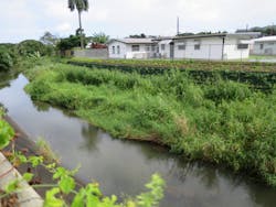
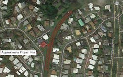
Over the past 40 years, high-flow events in the Kaneohe Stream have caused progressive erosion and degraded streambank integrity in north-central Kaneohe on the Hawaiian Island of Oahu. The problem along the eastern bank was exacerbated after a concrete lining was installed along the western bank in order to protect residential properties there.

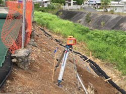
As part of Hawaii’s National Pollutant Discharge Elimination System (NPDES) Erosion Prone Area Improvements Program, the City and County of Honolulu was able to establish potential funding and to authorize a streambank stabilization project for a 330-foot (100 meter) stretch along the eastern bank (see Figure 1 A) in 2014. The project guidelines for the project focused on a softer, more natural reinforced vegetative system, in contrast to the concrete lining on the opposite side of the stream channel (see Figure 1 B).

Project Development
Initial geotechnical design for reconstructing and vegetating the streambank was based on a compost-sock structure with included geogrid wraps to provide a geosynthetic-reinforced “wall” ranging from 4 to 8 feet high. ParEn Inc., dba Park Engineering of Honolulu, HI, was responsible for civil design and developed the construction drawings and specifications. STRATA Inc. of Boise, ID, conducted the geotechnical fieldwork, soil testing, and geotechnical design of the wall.

During municipal review of the proposed project’s design and construction specifications, the Hawaii Department of Health (Clean Water Branch) provided specific review comments objecting to the use of compost socks for the wall facing, with the two major concerns.The first was the leaching of undesirable organic compounds from the compost filling into the waterway, and second was the eventual environmental breakdown of the sock fabric and the geogrid, which would release plastic fibers and microplastics into the waterway. Other concerns also included the lack of long-term durability if biodegradable materials (such as jute or coir fiber) were to be used in an alternative design.
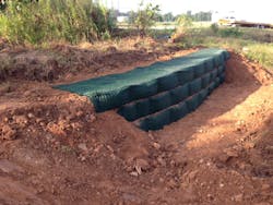
As a result, in 2015, the geotechnical design was redone and eventually changed to a geosynthetic wrap-face system (as seen in Figure 2) that relies on using native soil as infill for the wraps. The system uses an engineered polypropylene HPTRM (High Performance Turf Reinforcement Mat) known as PYRAMAT-75 with long-term UV stabilization and antioxidants to resist chemical degradation, providing a 75-year life expectancy when exposed to sunlight. This unique, engineered, geosynthetic vegetated wall system is a Propex GeoSolutions proprietary product known as PYRAWALL, and it was approved and selected for the Kaneohe Streambank Project. “The City wanted a durable green solution, making PYRAWALL a great fit by using the desired vegetation and providing an aesthetic, engineered, green wall system,” says Drew Loizeaux, P.E., engineering services manager at Propex Operating Company.
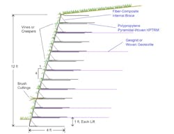
Wall ComponentsThis wall system is comprised entirely of three engineered geosynthetic (i.e., polymeric) components, with no metal or concrete or short-lived biodegradable materials. First, the pyramidal-woven polypropylene HPTRM for the face wrap to provide a reinforced soil mass near the wall or slope face and to prevent surface erosion as vegetation is established. Second, fiber-composite (nylon/fiberglass blend) internal braces comprised of snap-together bars that stand-up a 1-foot section on the HPTRM to allow soil infilling and compaction to form horizontal lifts within the reinforced-earth structure. Third, for walls higher than about twice the HPTRM wrap width, additional length is added to the soil reinforced-earth backfill zone using HDPE (high-density polyethylene) or PET (polyester) geogrids or woven geotextiles (Miller, 2018). These layers are buried within the backfill zone and are not exposed to UV light. A schematic for a typical PYRAWALL installation is shown in Figure 3. A case study describing a typical installation for a steep highway embankment was presented by Miller & Loizeaux (2019).

Geotechnical Evaluationand Design
Due to limited equipment access to the project site, geotechnical investigation and sampling relied on hand tools (such as a post-hole digger) that allowed for excavating three test pits to a maximum depth of 3.7 feet (1.13 meters) to identify and describe subsurface soils. Laboratory testing included the following:

  • Natural Moisture Content & Dry Density—ASTM D2216, ASTM D2937
  • Particle-Size Analysis—AASHTO T-27 and ASTM D1140
  • Atterberg Limits (liquid limit and plasticity)—ASTM D4318
  • Classification of Soils for Engineering Purposes—ASTM D2487
  • Direct Shear Strength of Soil—ASTM D3080
  • Laboratory Compaction Characteristics of Soil (Maximum Dry Density and
  • Optimum Moisture Content)—ASTM D1557
The soil was classified as Silty Sand (according to the Unified Soil Classification System), having moderate shear strength with an estimated cohesion of 460 pounds per square foot (psf) and an angle of internal friction of 31 degrees. Compaction testing indicated an estimated maximum dry density of 88.5 pounds per cubic foot (pcf) at optimum moisture content of 31.5%.

For geosynthetic reinforced-soil wall design, the focus is on evaluating engineering stability against the following potential failure modes (Koener, 1998, Berg et al., 2009):

  1. base sliding
  2. overturning (i.e., rotational tipping of the wall)
  3. exceeding foundation bearing capacity
  4. internal failure of the geogrid (i.e., rupture or pull-out)
  5. large-scale global slope failure

All of these potential modes were checked and evaluated using accepted geotechnical stability analyses, which showed that standard design criteria were met for a wall system 5 to 8 feet high, with 4-foot wrap embedments of PYRAMAT-75, and with an overall face angle of 1H:3V (71 degrees) which included a mid-height step to be used as a planting bench.

Soil compaction control during construction is critical to the long-term performance of these reinforced-earth structures. For this project, a nuclear moisture-density gauge (per ASTM D6938) was used to confirm that the contractor achieved the specified soil density at or near the optimum moisture content via mechanical compaction of the infill soil. For small compaction equipment, such as vibratory plate compactors, the thickness of soil compaction lifts often was limited at 6 to 8 inches in order to achieve the specified density. Effective compaction monitoring and verification help reduce the potential for differential settlement, which may adversely affect long-term performance.
Construction OperationsThe project bidding process resulted in the contract being awarded to Prometheus Construction of Kapolei, HI. Material costs for this vegetated wall system are comparable with those for segmental block walls, but the labor and construction costs for this project were high due to limited site access in the residential neighborhood and to ancillary expenses associated with working in a stream channel. As much as possible, on-site soil was used to construct the reinforced-soil zone behind the wall facing, but insufficient available soil volume forced the contractor to import similar soil and use a conveyor system to move soil from an access point on a residential street, across private property, and to the wall site along the stream.
“Site accessibility, which was through a residential side yard, was a big concern for this project,” says Steven Harano, P.E., project manager with ParEn Inc. “PYRAWALL was ideal in that the material could be hand carried and rolled out at the project site. The tiered landscape concept allowed for incremental levels to receive vegetative ground cover, which provided a more ideal and natural look to the streambank. Another desirable aspect was the high life-expectancy of the material.”

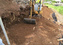
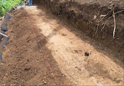
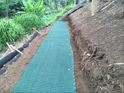
Site Grading and Subgrade Preparation: Because this geosynthetic wall system must be founded directly on native soil or approved structural fill, subgrade preparation involved vegetation removal and grubbing, followed by using a mini-excavator with smooth-blade bucket to remove topsoil and organic detritus in order to reach native, undisturbed soil (Figure 4) and provide a smooth platform to place the initial wrap-face lift. Line and grade for the wall base were surveyed and marked with paint or string-line.

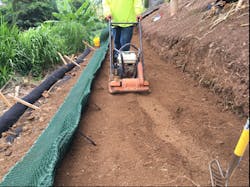
The level pad of native soil then was proof-rolled and compacted to assure a tight, dense soil structure with no soft spots (Figure 5). Compaction equipment included a vibratory plate compactor and a thumper-type compactor, both of which were small enough to use effectively in the narrow working area.

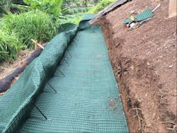
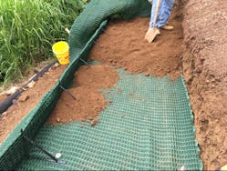
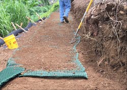
Wrap-Wall Construction: The HPTRM roll width of 8.5 feet (2.6 meters) allows for a bottom width of 4 feet, a lift height of 1 foot, and a top-flap layback width of 3.5 feet. After the internal braces were installed at a regular 24-inch spacing, the long section of HPTRM was placed on the level pad, the front edge properly aligned, then the fabric stretched taut in both directions and pinned down (Figure 6). Backfill soil then was placed and spread, then compacted in two 6-inch lifts (Figure 7) to fill the wrap-lift to the brace height.

The first wrap-lift was completed by pulling back the top flap over the compacted soil, pulling the fabric taut then pinning it down (Figure 8). A thin layer of soil then was spread across the fabric (Figure 9) and the second wrap-lift completed in a similar manner, then so on for the remaining lifts.

Because the HPTRM wrap-face system is flexible, the curve required by the wall alignment was achieved easily for each successive lift by cutting the horizontal HPTRM sections perpendicular to the wall face, and then overlapping the cut fabric accordingly to match the curve shape.

During the construction period of July to October 2018, the site was affected by minor flooding due to Hurricane Lane in late August. The high flow in Kaneohe Stream reached the base of the wall pad but did not cause any damage to the partially constructed wrap-face wall. However, the heavy rainfall and wet site conditions caused a work delay of about two weeks while waiting for the soil to dry out and allow proper compaction again.

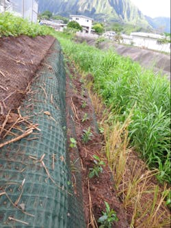
Vegetation Planting: Typically, during infilling of each wrap-lift, grass seeds or stolons can be added to the soil directly behind the HPTRM at the face. If desired, additional seeding can be achieved post-construction by hydroseeding the completed wall. However, for this project the design specified planting plug-stock through small cuts in the woven fabric (not prone to raveling), which included vetiver grass along the wall base, hopseed sprawling shrub on the planting bench, and white leadwort ground cover at the top (Figure 10).

If needed, temporary irrigation can be used to help new plantings get established. For shoreline applications, lower wrap-lifts planned to be below average water level may be filled with coarse granular backfill (to allow free movement of water), then overlying lifts transition to finer-grained infill soil above the waterline to support wetland vegetation. This wall system also is ideal for saltwater applications using brackish-tolerant plant species, because the geosynthetic components are chemically inert and do not corrode.

By using internal seeding and post-seeding via hydroseeding, excellent grass cover can be established quickly even in northern climates, as shown by a similar wall constructed near St. Paul, MN, in 2019 (Figure 11).

SummaryThis geosynthetic, vegetated wrap-face wall system provided an excellent remedy for bank reconstruction and stabilization along a residential section of the Kaneohe Stream. This system was selected because not only because on-site site soil could be used, but the fabric’s durability (projected 75-year life) and its ability to provide immediate erosion protection while promoting vegetation establishment was also an advantage. Straight and curved alignments are possible, and the geosynthetic wrap-face wall is especially well-suited to streambank, wetland, shoreline (including stormwater detention ponds), and coastal applications. 

References
Berg, R.R., B.R. Christopher, N.C. Samtani, 2009. Design of Mechanically Stabilized Earth Walls and Reinforced Soil Slopes. Publ. No. FHWA-NHI-10-024 and 025; USDOT, Federal Highway Administration.

Koerner, R.M., 1998. Designing with Geosynthetics, 4th Ed.; Prentice-Hall.

Miller, S.M., 2016. “Breakthrough Technology for Vegetated Retaining Walls and Slopes Using Internally Braced, Wrapped Geosynthetic Structures.” Environmental Connection 10(3): 21–25.

Miller, S.M., 2017. “Internally Braced, Geosynthetic Wrap-Face Vegetated Walls and Reinforced Soil Slopes,” Geosynthetics, Vol. 35, No. 5: 24–33.

Miller, S.M., & D. Loizeaux, 2019. “Highway Embankment Construction Using a Geosynthetic Wrap-Face Vegetated Wall System,” Proceedings, IFAI Conference, Houston, TX, (Paper No. 1222): 793–803.
About the Author

Stanley Miller

Stanley Miller is professor emeritus, Department of Civil Engineering, University of Idaho, currently working part-time as an independent engineering consultant. He has over 35 years experience in geotechnical engineering, slope stabilization, geosynthetic-reinforced earth structures, and erosion and sediment control.

Related

Home

Propex Global

March 20, 2020