Denver is a city in transformation. Over recent years the city has averaged close to 2% annual growth, adding more than 13,000 people per year. This growth, combined with the millennial trend to prefer denser communities with high-quality “urban life,” is causing a pronounced densification of Denver’s urban core, where some neighborhoods have seen greater than 50% growth in just seven years. As properties in these areas have become desirable, land values have soared. From a water-quality perspective, while increased density and impervious areas are compounding runoff and water-quality problems, there are fewer areas available to construct water-quality treatment facilities—especially large, traditional, single-function facilities like extended detention basins (EDBs). The result is a strengthening mandate to design and implement multipurpose green infrastructure (GI) facilities that can fulfill the necessary water-quality treatment for municipal separate storm sewer system (MS4) requirements and peak-flow reduction, while providing other benefits such as mitigating heat island effects and providing essential aesthetic, experiential, and environmental value to surrounding districts and neighborhoods.
Despite the obvious need, implementing GI in Denver has had its challenges. While the City’s recent growth, densification, and high land values would seem to favor the implementation of GI solutions over less attractive “gray infrastructure,” there are other regional factors that have slowed the pace at which they have been embraced—primarily the lack of the intense environmental and regulatory pressure (and fines) that cities with combined sewer systems (CSSs), such as Portland, Seattle, and Chicago experience, but which Denver, with no CSS, does not. In cities with CSSs, the cost of GI seems quite affordable when compared to the billions of dollars required for major sewer system overhauls. Comparatively, GI has been a tougher sell in Denver, where more traditional water-quality treatment has been considered a relatively affordable development cost, especially in less dense areas. Other significant challenges include implementation of plant-oriented solutions in Denver’s semi-arid climate with hot, dry summers with sparse, yet intense rainstorms, and cold, dry winters where temperatures can swing 50°F in a day. Salt-based de-icer chemicals used on roads during winter storm events, which ultimately end up in runoff, further contribute to the extreme and challenging conditions for the sustainability of stormwater BMP vegetation.
Despite the challenges, Denver is taking a bold step forward embracing GI as a fundamental approach to meeting its water-quality requirements. Up until 2013, Denver relied exclusively upon a robust maintenance program to meet its MS4 program requirements. The maintenance program began in 2003 and targeted 10 priority storm drainage basins that are regulated on dry-weather discharges for Escherichia coli (E.coli) by the Colorado Department of Health and Environment (CDPHE). The MS4 permit identified best management practices (BMPs) for implementation in the high-priority basins that included the following:
- storm sewer cleaning that included cleaning of storm sewer mains, laterals, siphons, catch basin inlets, and manholes to remove sediment and debris that might contain or contribute to the growth of E. coli
- sanitary sewer system pipeline investigation and correction program, through which sections of the sanitary sewer system with significant potential to contribute sanitary sewer seepage to the MS4 were identified and repaired
- storm sewer system investigations, under which inappropriate and/or illegal taps, sanitary sewer seepage, and other sanitary waste sources finding their way into the MS4 were identified and repaired
- storm sewer marker program, which installed markers or other signage to discourage dumping into municipally owned storm sewer inlets in areas with public access
- education and outreach program, which included development, documentation, and implementation of an education and outreach program focused on sources that are determined to have a significant potential to result in exceedances of the E. coli standard in discharges from the MS4 from residential, industrial, agricultural, and/or commercial sources
The maintenance program was generally effective, and progress was made in reducing E. coli levels and loads in dry-weather discharges from most of the basins, though a few remained above the waste load allocation. However, as mentioned above, increased densification and impervious areas within the city, and less space to implement traditional water-quality BMPs called for a more integrated water-quality approach. In 2013, the City and County of Denver took a step to build a more robust and sustainable stormwater program and hired a water-quality project manager with a background and focus on green infrastructure.
At that point, two planning efforts were started to advance the use of green infrastructure in Denver. One was the creation of a Strategic Stormwater Master Plan; the other was the development of the Ultra-Urban Green Infrastructure Guidelines (UUGIG). The Strategic Stormwater Master Plan, which is now referred to as the Green Infrastructure Implementation Strategy, is complete and outlines a stormwater quality prioritization (or scorecard) approach to prioritize watersheds within Denver that have the greatest need for stormwater quality improvement. The scorecard established a methodology for prioritizing both the major drainage basins and sub-basins, as well as identifying parcels for green infrastructure projects that could be implemented within the priority basins. Basins were scored based on primary and secondary criteria. Those attributes that are associated with stormwater quality and quantity are of primary concern, while secondary criteria included parameters such as park density, social justice, urban heat, and the transportation pollutant index (Figure 1).

The outcome of the application of the scorecard across all of Denver’s drainage basins resulted in the identification of six high-priority basins and five medium-high-level-priority basins (Figure 2). This prioritization allows Denver to give precedence to building green infrastructure projects where they are most needed, rather than randomly or in areas where projects can be most easily constructed. The scorecard also ensures that Denver avoids single-objective strategies and gets more from each investment by building projects that provide a host of citywide benefits.

Figure 2. The scorecard map rates drainage basins in the city for their suitability for green infrastructure investment.

Within each of the priority basins, both large-scale and site-scale green infrastructure projects have been identified with a focus on city-owned parcels, including the street right of way (ROW) and parks. On a large scale, green infrastructure refers to a network of parks, open spaces, drainageways, and floodplains that help mitigate the impacts caused by impervious (hard) surfaces. Site-scale green infrastructure refers to smaller engineered structural practices that are necessary to mitigate the impacts urbanization has on the hydrologic cycle. These systems mimic larger natural systems and use vegetation, soils, and roots to slow and filter stormwater runoff. Benefits of green infrastructure, regardless of scale, include improved water quality, reduced flooding risks, better air quality, urban heat island effect mitigation, reduced energy demands, climate change resiliency, and enhanced community livability.
The second program developed to kick-start green infrastructure in the city, the Ultra-Urban Green Infrastructure Guide, was rolled out in 2015. Prior to this, Denver lacked BMP guidelines that addressed the realities of its urban developing (and redeveloping) areas. The metro area’s drainage district, the Urban Drainage and Flood Control District (UDFCD), had developed a comprehensive criteria manual that provides guidance on a full range of stormwater treatment practices; however, its focus is on larger sites that can accommodate extended detention basins, constructed wetland channels, and grass swales. In Denver’s dense environment, these treatment BMPs weren’t always suitable. The City of Denver partnered with UDFCD to develop Denver’s UUGIG, which were intended to enlarge the toolbox of applicable treatment BMPs for both public and private projects. The BMPs covered in the guidelines include:
- streetside stormwater planters,
- bump-out stormwater planters,
- green gutters,
- green alleys, and
- tree trenches.
These practices were chosen for their suitability in Denver’s ultra-urban environment and in particular for use within the ROW. Treating street drainage is a top priority in Denver, as streets not only are a major source of stormwater runoff but also represent the largest source of urban pollutants, including sediment, heavy metals, nutrients, and trash. The guidelines include planning and engineering criteria for site-scale green infrastructure, and include recommendations on siting/urban design, aesthetics, planting/vegetation, and maintenance.
Using Denver’s Ultra Urban Green Infrastructure Guidelines
The following section walks the reader through the design guidance provided in the UUGIG for one of the most frequently used BMPs, the streetside stormwater planter. The manual provides similar instruction for the other BMPs mentioned above. Those interested in viewing the full document can find it online on Denver’s at www.denvergov.org/content/dam/denvergov/Portals/705/documents/guidelines/PWES-013.0-Ultra_Urban_Green_Infrastructure_Guide.pdf.
Streetside Stormwater Planters (Abridged Version)
A streetside stormwater planter is a type of bioretention facility located within the street ROW in the amenity zone between the street and the sidewalk. It is intended to provide water-quality treatment of runoff from the street and adjacent pedestrian zone and may also be designed to treat runoff from adjacent private development. Stormwater runoff enters the streetside planter through a curb opening and chase-type inlet, spreads over the planting media, infiltrates vertically downward, and exits through an underdrain. Treatment processes include filtration, absorption and adsorption, and plant uptake. A variety of vegetation can be established in these planters, including grasses, perennials, shrubs, and a limited number of adapted trees. Figure 3 illustrates how a streetside stormwater planter can be integrated into the amenity zone of a typical street section and how planters can be sited within a block.

Pedestrian Considerations and Geometry. Planter Edge Barrier: A visual and physical barrier along the perimeter of a planter is necessary to discourage deliberate or inadvertent entry by pedestrians. In general, a 6-inch or higher barrier parallel to the sidewalk is recommended on the “long” sides of the planter parallel to the street, and a 15-inch or higher barrier is required on the “short” sides of the planter perpendicular to the street. Pedestrian safety must also be kept in mind when establishing the maximum depth of the planter, which should generally not exceed 16 inches. Examples of barriers are shown in Figure 4.
Sidewalk Drainage:Small openings or gaps in the edge barrier opposite the street are typically provided in streetside stormwater planters to allow drainage from the site and sidewalk to enter the planter.
Step-Out Zone: Denver requires a 2.5-foot step-out zone behind the back of curb in all locations where parking is (or will be) adjacent to the curb. Where parking is not planned adjacent to the curb, a 1.5-foot setback is required.

Figure 4. Planter barrier examples
Planter Length: Planter length for any planter depends on required access from one side of a planter to the other and required treatment volume. The maximum length of streetside stormwater planters in Denver is 40 feet, so as to provide reasonable access for pedestrians to exit a vehicle and get to the sidewalk. In addition, all access points adjacent to/around the planters must provide a minimum of 4 feet clear. In highly active areas, it may be appropriate to provide more frequent or wider access points; however, the minimum recommended length is 20 feet. (The maximum length of the planters, based on street slope, has been calculated and is shown in a figure in the guidance manual, assuming sidewalk drains are provided as shown in the details.)
Planter Width: Planters may be made as wide as possible within the available ROW based on desired widths of the step-out zone and sidewalk. Although these dimensions may vary, a typical width for a streetside stormwater planter on a Denver arterial street, with a stepout zone of 2.5 feet, is 6 feet. Planters that have a minimum inside width of 5 feet can incorporate trees. For situations where less ROW is available, the width may need to be reduced; however, there is a practical minimum below which it may not make sense to incorporate this type of BMP.

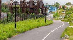
Figure 5. Example of streetside stormwater planter in urban environment
Uses and Recommendations. Streetside stormwater planters can be created in mid-block locations or near corners on streets that do not receive deleterious amounts of deicing salts. Sizing and locating planters requires a determination of the area draining to the planter. There is a specific drainage area associated with a certain size of planter and it is necessary to site the planter in a location that has this upstream area draining to it. Typically, the upstream end of a block is not as effective a place to install a planter (due to a lack of contributing drainage area) compared to a mid-block or lower end of block location. Siting streetside stormwater planters is also influenced by the presence of a storm drain system; ideally, a nearby inlet or manhole provides a convenient location to which to discharge a planter underdrain.
If serving just the public ROW (street and pedestrian zone), three to four streetside stormwater planters measuring 6 by 40 feet (outside dimensions) can satisfy the water-quality requirements for an impervious area measuring 420 feet (a typical city block) by 30 to 34 feet (street crown to ROW) for Denver’s local and collector street classifications. Five to seven streetside stormwater planters this size would be necessary to serve the water-quality needs of a city block (crown to ROW) of Denver’s four-lane and six-lane arterial classifications. If a portion of the adjacent private development is also served, additional planters would be necessary.

Figure 6. Denver Green Infrastructure Group’s planned demonstration project at 21st and Broadway
Planter Aesthetics and Urban Design. Streetside stormwater planters can be valuable amenities to the urban landscape if designed properly. Designers should take design cues from the surrounding streetscape (if improved) and/or special district urban design elements and materials. Planters should match or complement the larger urban context, as well as add value to the adjacent properties. Because planters are located within the public right of way, it is imperative that the design detailing for the planters is uniform within each block, and preferably within each district or neighborhood.
Additional Design Considerations. The selection and design of streetside stormwater planters and other green infrastructure practices is driven by a site’s physical characteristics, including soils, groundwater, development conditions within a watershed, Denver’s semi-arid climate, and the unique system of administering surface water rights.
Soils: Soils with good permeability, typically associated with hydrologic soil groups A and B, provide opportunities for infiltration of runoff and are well suited for streetside stormwater planters and other infiltration-based practices—sometimes without the need for an underdrain system. Even when soil permeability is low, these types of practices may be feasible if soils are amended to increase permeability or if an underdrain system is used. In some cases, however, soils limit the use of infiltration-based practices. When soils with moderate to high swell potential are present, infiltration should be avoided to minimize damage to adjacent structures due to water-induced swelling. In these cases, filtration designs can still be used if an impermeable liner and underdrain system are included in the design. In all cases, a geotechnical engineer should be consulted when designing infiltration practices near structures to evaluate the suitability of soils for different practice types and establish minimum distances between infiltration practices and structures. Regardless of soil type, a curtain liner may be required if the facility is located close to a building with a basement.

Figure 7. Aerial photo showing proposed site for neighborhood green infrastructure facility in southwest Denver
Groundwater: Shallow groundwater on a site presents challenges for green infrastructure practices that rely on infiltration and for facilities that are intended to be dry between storm events. Shallow groundwater may limit the ability to infiltrate runoff or result in unwanted subsurface storage of groundwater in areas intended for storage of the WQCV (e.g., the porous sub-base of a permeable pavement system or in the bottom of an otherwise dry facility such as an extended detention basin). Groundwater quality protection is an issue that should be considered for infiltration-based practices. Infiltration practices may not be appropriate for land uses that involve storage or use of materials that have the potential to contaminate groundwater underlying a site (i.e., “hot spot” runoff from fueling stations or materials storage areas). If groundwater or soil contamination exists on a site (i.e., a brownfield), and the contamination will not be remediated or removed as a part of construction, it may be necessary to avoid infiltration-based practices or use a durable liner to prevent infiltration into areas contaminated with pollutants that could be mobilized by stormwater.

Figure 8. Engineer’s preliminary diagram showing potential water-quality treatment area in blue
Semi-Arid Climate: Denver’s semi-arid climate requires modifying green infrastructure practices adopted from other US locations. Stormwater facilities typically must be landscaped with drought-tolerant plants (xeriscape) with a focus on native plants, since they use less water and perform better in the semi-arid environment. A mix of North American natives can be used to develop a plant palette that will tolerate both periodic flooding and drought. Though native species will likely need supplemental irrigation during establishment and during periods of drought, non-native plants generally will not survive without irrigation. Rain events in Denver tend to be high-intensity and infrequent, resulting in a water-quality event that is heavy with sediments and other pollutants that have accumulated since the previous storm. As a result, forebays, pre-sedimentation basins, or other forms of pretreatment are recommended to remove some of the particulate matter before it reaches the green infrastructure facility.
Surface Water Rights: Surface water in Colorado is administered through a priority system and is carefully administered by the Colorado Division of Water Resources. Water-quality treatment may be considered a “consumptive use,” triggering the need for an augmentation plan if designers don’t comply with state standards. Specific limitations for water-quality facilities include the following:
- Stormwater detention areas must release all of the water detained from the site within 72 hours of the end of a precipitation event, should be designed to release the water from the site as quickly as downstream conditions allow, and must be designed to minimize consumption from vegetation.
- Infiltration areas must be designed to infiltrate the water into the underlying aquifer as quickly as possible, shall not result in an exposed water surface beyond 72 hours after the end of a precipitation event, and must be designed to minimize consumption from vegetation.
- Stormwater may not be diverted from detention, infiltration, or green roof areas for any beneficial uses.

Figure 9. Plan and perspective of the “architectural” green infrastructure concept
Materials for Streetside Stormwater Planters. Bioretention Media: Material should be consistent with the criteria outlined in the specifications. A minimum media depth of 18 inches is appropriate for most applications. When trees are used, increase the depth of the media to 36 inches.
Underdrain and Filter Material: An underdrain system is used to collect and drain the filtered stormwater from beneath the bioretention media. The underdrains should be slotted-wall PVC pipe within the BMPs and transition to solid-wall PVC pipe outside the BMPs.
Flow Control Structure: A flow control structure is recommended at the downstream end of the BMP underdrain to house an orifice to limit outflow to the specified release rate. It also provides a means of overflow and an opportunity to monitor and adjust the top of the WQCV within the BMP.
Planter Walls: Walls surrounding the planters and green gutters are recommended to contain the media and WQCV, to facilitate easier maintenance and constructability (especially in retrofit projects), and to decrease the potential for saturation of the adjacent soils. Several options for wall construction are available in today’s marketplace. Walls can be constructed out of concrete, both cast-in-place and pre-cast, and can be colored, stained, and stamped. Walls may also be constructed out of blocks or bricks with mortar and could integrate stone elements. Regardless of the type of construction, a structural engineer shall be responsible for designing and detailing the walls and other structural elements of the BMPs. The designer should take into account the desired aesthetic appearance, structural integrity, and street slope among other factors when laying out and designing planter walls. The details show the bottom of the walls even with the bottom of the planting media, with an 8-inch-deep excavation between the walls to place the layer of filter material. Alternatively, the walls could extend to the bottom of the 8-inch-deep filter layer. In either case, the designer needs to specify subgrade conditions necessary to ensure a suitable foundation for the walls and reduce the potential for settling.
Liners: It is the responsibility of the designer or geotechnical engineer to specify whether a liner is required for a streetside stormwater planter or other green infrastructure BMP, depending on the soils, adjacent structures and pavements, etc.

Figure 10. Plan and perspective of the “radial
agrarian” green infrastructure concept
Vegetation: Vegetation is a key component of green infrastructure BMPs. Plants improve infiltration rates, provide water and nutrient uptake through plant roots, and generally improve water quality though biological processes. Plant species selection and planting design for the planters is a critical design consideration that can greatly affect the overall success and public acceptance of these BMPs within the public ROW. Growing conditions in planters, especially those in ultra-urban environments, will generally be harsh, so plant selection is important. In general, plants for use in planters should be:
- drought tolerant;
- flood/inundation tolerant;
- mid-sized (taller than 12 inches, shorter than 4 feet);
- upright in form;
- salt tolerant (especially for planters on streets treated with magnesium chloride de-icer);
- able to thrive in low-fertility, sandy soils (no fertilizer or supplemental compost allowed in planters); and
- non-invasive.
In addition, ideal plant material should be native, have long flowering periods (if applicable), be attractive year-round, be long-lived (5 to 10 years), and be an aggressive grower.
Planting Considerations:
- When selecting vegetation, consider the depth of the planter as well as the potential plant height so that plantings do not exceed 42 inches above the sidewalk elevation near intersections to provide required visibility.
- Irrigation is necessary to establish the vegetation.
- All plants should receive approximately an inch of moisture (combined rain and irrigation) per week for the first growing season to promote successful establishment, requiring an automatic irrigation system or close monitoring by a maintenance staff, an available water source, and hand irrigation.
- Watering or irrigation of plants after establishment shall be on an as-needed basis. Plants should be monitored a minimum of once every 10 days in the second season, and once every two weeks thereafter for watering needs.
- To facilitate ease of maintenance and a neat appearance, and to reduce areas available for weed growth, it is recommended that planting designs employ masses of fairly tightly spaced plantings. Spreading plant materials can be used but require an increased level of maintenance early in the life of the facility so that weeds do not become established.
- Planting beds may be mulched with 1 to 2 inches of shredded wood mulch to reduce weed growth or left unmulched if plant density is sufficient to cover 75% or more of the bioretention media. The wood mulch should be finely shredded in a manner that creates a fibrous mass that meshes together and resists movement. The thickness of the mulch should be considered part of the bioretention media depth; if 2 inches of mulch are used, the actual thickness of bioretention media should be adjusted from 18 inches to 16 inches. The top of the mulch layer is considered the bottom of the WQCV.
Vegetation Maintenance Considerations:
- Inspections for sufficient moisture will be required as needed throughout the growing season (March through October). Inspections should also consider limitations with regard to the height of vegetation above the sidewalk elevation as it relates to visibility.
- All plantings require monthly hand-weeding during the growing season to ward off infestations of deep-rooted perennial weeds such as smooth brome, Russian thistle, leafy spurge, bindweed, and bluegrass. Prolifically seeding weeds such as cheatgrass, dandelions, prickly lettuce, spotted spurge, purslane, black medic, alfalfa, and yellow and white sweet clover must be vigilantly removed promptly to prevent them from going to seed and creating long-term infestations.
Tree Species and Placement. Trees are encouraged and can be included in streetside stormwater planters. Trees are typically centered in the amenity zone between the step-out zone and the sidewalk. Consideration needs to be given to width requirements for the sidewalk when placing trees. Per the city forester, trees may be placed only in areas with a minimum width of 5 feet. In general, it is recommended that trees be placed 4 to 6 feet from the back of curb.
Green Infrastructure Becoming a Reality in Denver
Since their inception, the Ultra-Urban Green Infrastructure Guidelines have been well received in Denver and have been used for the design of a number of capital street reconstructions. However, it has taken some time for these projects to reach fruition. Currently, several major improvement projects under construction will put green infrastructure “on the map” in Denver (Figure 6). For example, the Brighton Boulevard Reconstruction project in Denver’s trendy RiNo neighborhood will construct more than 100 streetside stormwater planters within the ROW. Another ROW project under construction at 21st and Broadway will showcase a number of BMPs from the UUGIG, including a green gutter, green alley, and tree trenches. Denver has several other projects planned and under construction that will use the new criteria.

Figure 11. Plan and perspective of the “cascading
rings” green infrastructure concept
Case Study: The Lowell and Evans Green Infrastructure Project
Denver’s approach to creating green infrastructure is more than just incorporating environmental benefit into infrastructure projects. It is about maximizing benefits to the environment and the community at large. It is about not creating single-purpose infrastructure, but rather multi-beneficial projects that achieve a wide range of objectives that add value to the community. With care and thoughtfulness, infrastructure can add value and interest to our urban environments. It can influence the way people think about their community and even how they take care of it. It can create memorable places for the community to gather. It can teach lessons about the impacts that human civilization has upon our natural systems, and how we can mitigate those impacts. Sometimes it takes a little more effort. It means opening up design processes to allow for public input. Sometimes it might cost a little more, but that is not necessary.
The Denver Ultra-Urban Green Infrastructure Guidelines, while creating easy standards for developers and designers working for the City to follow, also create a departure point for creating customized solutions to water quality opportunities. Based on the Green Infrastructure Implementation Strategy’s ranking of high-potential drainage basins for green infrastructure, and on suggestions from members of the community, a promising site for green infrastructure/water-quality treatment was identified in an established neighborhood at Lowell Boulevard and West Evans Avenue in southwest Denver (Figures 7 and 8). The site is in a basin rated as having a “medium-high” score on the implementation plan’s scorecard (see basin 8 in Figure 2, the scorecard map) and was identified as a good potential pilot project for the Green Infrastructure Group’s initiative. The site is an overly wide asphalt pavement area that was the result of a need to transition-connect slightly off-kilter arterial roadway alignments between adjacent developments on either side of Evans Avenue. This unnecessary area of pavement has been mostly unused, except as occasional neighborhood overflow parking, for more than 50 years.
The City of Denver’s Green Infrastructure Group hired a consultant team consisting of an engineer (Muller Engineering Company) and a landscape architecture firm (Stream Landscape Architecture) to work with them to perform a feasibility study to determine if the site was able to provide meaningful water-quality treatment while complying with the city’s roadway and development criteria. The consultant team also worked with city staff to conduct a public engagement effort to gauge community support and concerns for the project. Two initial public meetings were held, with opportunities for attendees to vote their preferences in terms of aesthetics, amenities, vegetation types, etc. The City was open-minded as to what type of character facility it would explore and looked to the community to help define the design parameters. A good portion of the public meetings was spent educating people about the need for water-quality treatment to mitigate the effects of urbanization. Take-aways from the meetings provided the City with the following guidance:
- The rain garden should provide a place where members of the community can pause to observe and enjoy the features and vegetation of the garden, but it should not be designed to encourage groups to gather and hang out, given the closeness to private residences.
- The style should be orderly, but not too regimented, with the area around the rain garden relatively open and maintaining good visibility.
- Interpretive features like plant identification would be appreciated.
- Bottom line, the rain garden must be an attractive and well-maintained facility, with healthy plants and good maintenance and weed control.
Overall Site Design Parameters. After working through the development requirements for the street ROW, including parking, sidewalk, tree lawn, etc., the engineers set the framework for the green infrastructure facility.
Site Capacity: The area of the contributing drainage basin (due south of the site and flowing to the north in the gutter pan on the east side of Lowell Street) that the site can receive by normal surface flow is 2.4 acres, which generates a WQCV of 0.07 acre-feet, or 3,050 cubic feet. The site’s usable area for water-quality treatment, after subtracting parking spaces, tree lawns, sidewalks, and set-backs from adjacent properties, is approximately 4,700 square feet. With local BMP design guidelines recommending an average ponding depth of 12 inches for rain gardens, the percentage of the “usable” site that would need to be devoted to the rain garden function to accommodate the WQCV of 3,050 is 65%, with the rest of the space required for a seating area, forebay (sediment pretreatment), landscape buffers and planting strips, and potentially for landscape slopes to contain the rain garden. (Given this information, an early design option that had been explored, which would have doubled the amount of stormwater delivered to the site by capturing runoff from the west side of Lowell and directing it to the site via an inlet and pipe across Lowell, was rejected. It would have increased the WQCV well beyond the recommended capacity of the site and would have been a detriment to the overall design of the facility due to the need to lower the entire rain garden to accommodate the piped flows.)
Topography: The site (and the proposed gutter flowline) slopes from south to north at approximately 3%, so it was determined early on that some degree of terracing would be required to maximize capacity of the site and to prevent the cells of the rain garden from becoming too deep.
Utilities: An existing water line bisects the primary rain garden area and will be relocated as part of the project.
Private Access: An access drive crossing from Lowell Street to an adjacent residence (for future potential garage access) at the northern end of the site renders use of the northern tip of the site impractical for water quality.
Irrigation: Denver’s semi-arid climate makes it extremely difficult to keep the typical rain garden plant species that can withstand prolonged inundation healthy and attractive during the summer months, when rainfall can be quite scarce. As a result, the city’s UUGIG calls for all rain gardens installed by the city to be irrigated.
Concept Development. The team developed the following three concepts that span a range from an ordered (“architectural”) approach to a more naturalistic approach. Each was intentionally varied in its characteristics (forms, public gathering, planting approach) to elicit responses and opinions from the public.
The first concept developed, “architectural,” was based on a simple modern design approach, using straight concrete walls to create terraces set a little off of perpendicular to the main sidewalk, creating interesting planting areas and seating spaces along the sidewalk edge (Figure 9). This concept accomplished a number of community and design team objectives including an efficient use of space for the rain garden areas and dispersed and small-scale seating areas. The individual terraces were designed to contain approximately 12 inches of water before spilling to the next lower terrace. As an aesthetic touch, a concrete edger would appear to continue the terrace walls on the opposite side of the sidewalk, through the tree lawn area.
The second concept developed, “radial agrarian,” was inspired by the idea of the water-quality rain garden as an agrarian concept, with rectilinear “plots” arranged in cascading fashion along curved rows that stepped down not only from south to north, but also from west to east, creating an overall rain garden scheme that closely followed the existing contours of the site (Figure 10). While the longer “concentric” walls would be concrete, the shorter “radial” patterned walls could be simple steel edgers. To tie the overall concept together, the radial walls would be continued as a flush concrete edger though the tree lawn on the opposite side of the sidewalk. The planting concept for this concept was to create a bold pattern of contrasting plant materials in each “cell” that would appear much like a small-scale truck farm or a farmhouse garden. It was thought that by creating a very restrained palette of plant material in each cell (maybe one or two plant species), maintenance workers would have an easier time identifying interloping weed species, which would stand out from the intentionally planted plants. A small crescent-shaped “mini-plaza” nestled in the center of the concentric and radial patterns would create a seating and observation space for the garden.
The third concept, “cascading rings,” was the simplest of the three and was intended to minimize the number of walls and amount of overall structure in the design (Figure 11). The sides of each terrace were to be contained by landscaped earthen slopes as opposed to walls. The number of terraces was reduced to three by expanded their size, which eliminated the number of walls, although the height of the walls got somewhat higher to take up the additional grade between terraces. The intended planting approach for this concept was to have more variety in the planting than the other two concepts. Also, with the larger terraces, there is more room to insert slightly larger woody material, especially because there will likely be a desire to reduce the impact of some of the higher terrace walls. The seating and observation space for this concept is essentially the uppermost of the cascading rings, abutting the sidewalk along the south edge of the space.
Status of Decision on Concept Selection. City staff and the design team were somewhat surprised that there were not a lot of strong opinions for or against any of the preliminary design concepts. General consensus preferred concept 3, the cascading rings concept; however, most people would have been happy with any of the choices. Feedback did stress the importance of having attractive landscape surroundings around the rain garden, including an alley of trees along the west side, landscape plantings along the walkway, and a general approach that showed the community that this facility was a “special” place. The City and the design team are now moving forward with the construction document phase of the project. Project construction is anticipated in 2019.