“In the solid waste industry, planning for future waste disposal capacity is something we have to start years in advance,” says Katie Sandoe, chief commercial officer with the Lancaster County, PA, Solid Waste Management Authority. “We are a heavily regulated industry, and permitting for expansions, whether new or existing, takes a very long time.” In the early 2000s, LCSWMA began recognizing that it would run out of landfill capacity at its existing site around 2019. At the time, that would have meant contemplating “expansion on another site,” says Sandoe. In her role, she directs the successful implementation of LCSWMA’s capital projects and strategic initiatives, as well as cultivating a strong community focus and proactive public engagement philosophy within the organization.
Sandoe explains that around 2009, LCSWMA officials became aware of the technological advancement of the mechanically stabilized earthen [MSE] berm technology that would allow operators to utilize an existing site footprint to add additional capacity for landfill disposal volume. The key was to expand upward rather than outward. “We recognized that this was the most responsible pathway for us to move forward from a fiscal perspective, from a social perspective, and from an environmental perspective,” she says.
A Gentler Footprint
“From an environmental perspective, by deploying the berm to expand vertically rather than laterally, we will be able to continue utilizing the existing footprint of the original 93 acres of lined area,” she says. “By using this MSE berm technology, we’ll be able to obtain an additional 6.4 million cubic yards of capacity over the complete life of this expansion, while only having to increase the footprint of the landfill by roughly nine acres.”
Rather than the county running out of landfill disposal space by 2019, says Sandoe, implementing the MSE berm “translates to an additional 18 to 20 years of additional service to our community, depending on how quickly volume expands in response to economic growth.”
She notes, “Were using an existing footprint, so we don’t have to go offsite; we don’t have to site a new greenfield landfill. I believe the Pennsylvania Department of Environmental Protection has not sited a new greenfieldfor a couple of decades.”
From a fiscal perspective, LCSWMA’s MSE berm will allow use of the existing infrastructure on the landfill site, making it possible to continue using assets such as the scale house, the office, the leachate collection system, and the landfill gas plant. “Rather than having to find a completely different site, there is a cost savings to utilizing everything already there,” she says.
From a social perspective, she says, “South-central Pennsylvania has a very rich, long agricultural heritage. Since we were first established as LCSWMA in the mid-1980s, the goal has always been to minimize the consumption of land for disposal of waste.” To facilitate that ethos, LCSWMA has implemented an integrated system that combines recycling and using waste-to-energy technology. Using an MSE berm to facilitate vertical expansion represents another means to avoid consumption of land to accommodate landfill disposal volume.
Like Steep Stairs
Ben Allen, project manager for Arm Group, the geotechnical engineering firm on the project, explains that the MSE berm is designed to wrap roughly two-thirds of the way around the perimeter of the existing landfill. “It varies in height, rising up to 60 feet high in some locations. What it does is, instead of expanding laterally, it allows the landfill to expand vertically, to place more waste in a vertical fashion, and prolongs the life of the facility.”
Describing the system, he says, “It’s a soil berm that is reinforced with geosynthetics, allowing you to make the desired slope.” He describes the exterior slope as “near vertical.” He notes, “It’s like a 70-degree slope reinforced with the geogrid material that Tensar produces.” Erosion control matting covers the face, which is then vegetated.
“If you looked at it before the grass started growing, it would look like a very steep staircase. For every 18 inches you go up, you then go flat nine inches.” He says the design could be likened to the ancient step pyramids that also rise using a stair-step principle. “It’s the new natural wonder of the world,” he jokes.

Standing Up for Soil
Tensar’s uniaxial geogrid and biaxial geogrid were both used in the construction of the berm. Tensar uniaxial (UX) geogrids are manufactured from select grades of high-density polyethylene (HDPE) resins that are designed to resist elongation, or “creep,” when subjected to heavy loads for long periods of time. According to Allen, the uniaxial geogrid serves as the primary reinforcement, while the biaxial geogrid reinforces the face, “allowing that steep angle.”
He explains the structure with a comparison to reinforced concrete. “Everyone is familiar with reinforced concrete; this is not an entirely different concept from that. You need to put the reinforcement in there to achieve the desired slope. Soil doesn’t really stand up straight, if you were just to pour it out of a bucket, so in order to get a stair-step effect you have to reinforce it.”
Chris Vance, environmental market manager for Tensar International Corp., elaborates. By delivering high-tensile strength, he says, the geogrid “plays a similar role to steel reinforcement in concrete. You use different bearing strengths of steel to reinforce concrete. In this application, depending on how high you are going, how much fill will be behind it dictates what strength of grid you are using. The uniaxial grid gives the structure high-tensile strength in one direction to hold the soil slope. It holds it in place and lets the soil stand vertically behind it.”
Just underneath the final facing of the berm, he says, “Tensar’s biaxial geogrid—a grid with strength in both directions—is utilized as the face wrap of the berm. That gives the face its strength and holds the face in place. That’s what holds the erosion control mat, and the hydroseeded vegetation grows out of that.”
One of the characteristics that led to the selection of Tensar geogrids for this project is their resistance to degradation. “It is made of HDPE, which is the same type of material as what the [landfill] liners are made out of, so it will hold up. If any external elements get to it, it is inert to that, so they won’t cause any damage to the grid. And the biaxial geogrid secondary reinforcement is UV-stabilized with carbon black, which allows long-term strength and no degradation from UV sunlight,” explains Vance.
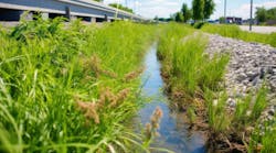
Allen notes that a small extension of the liner system was added, tying in with the existing liner. “The berm goes around two-thirds of the perimeter of the landfill, with the majority of the landfill well inside this perimeter. The working face of the landfill would not be close to the berm.” Eventually, he says, “The final slope of the landfill will basically come in and tie in with the berm once all of the waste is placed. There is a roadway and stormwater channel on top of the berm, and that final slope will come down and tie in very closely to the edge of the stormwater channel, and that will take any runoff from that slope.”
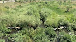
To complete the installation, a North American Green SC150 coconut-fiber erosion control blanket covers the face of the berm. “The erosion control blanket helps promote vegetation by holding moisture,” says Allen. “After hydroseeding with a native mix so that it blends in with the environment, that vegetation takes off.”
The berm is not physically tied to the landfill, explains Vance. “The pieces of grid are hooked together, and every 18 inches on the actual grid there is a layer of grid that lays in under the soil that is placed and compacted.”
Allen says work to construct this type of MSE berm “can be done any time of year,” but, he concedes, “Spring and fall are the best times to get good growth in Pennsylvania. As far as the construction of the system is concerned, you can do it year-round, but probably not in the winter, just because it’s harder to work with the soil.”
Growing in the Right Direction
“Pretty much every landfill will have some type of berm, whether that is just an earthen four-foot berm with no reinforcement or, as in the case of the landfill we’re discussing, a much larger berm to allow them to expand vertically,” says Allen.
“Most berms around landfills will be earthworks, and typically they have vegetated facing. There are quite a few berms in the northeast that use MSE technology,” including a number of other sites in Pennsylvania.
Vance explains, “This is a technology that is pretty common for this type of expansion in the Northeast, in Pennsylvania, Virginia, and New Jersey. It’s starting to expand out into the Carolinas and Georgia, where capacity is an issue and land availability is also an issue. It is becoming a more widely considered and used technology than 20 years ago.” However, he notes, “The conventional way of expanding landfill capacity is still expansion outward, when they have the room to do it.” Nonetheless, in the Northeast, “where regulators and controlling agencies have adopted it and allowed the use of it, people will use it a lot more regularly.”
He adds, “In the Northeast, space is at a premium; there are not a lot of places to go with a landfill. These are the places where you typically see these [berms]—places where facilities could not go outward and they had to go vertical.”
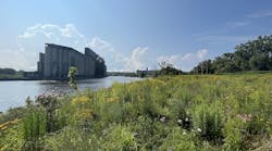
Nick Kohr, LCSWMA’s director of capital projects, says it is “most likely” the landfill will be transformed into a passive recreation area once it has reached full capacity and is retired from service. Already at the site, enhancing the landfill’s sustainable portfolio, two commercial-scale wind turbines generate power for an adjoining property owner. “We are right next to Turkey Hill Dairy. We supply electricity to them for their production line. Some of the other adjoining properties we already support with parkland and recreation,” he says.
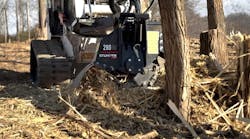
After installation of the berm, maintenance is straightforward, says Kohr. “You just have to watch and manage the woody vegetation. If any woody vegetation starts growing on the face of the berm, if it gets to an inch in diameter it would require pruning once in a while.”
Stage one of the three-stage expansion project at the landfill has been completed. “It has grass growing on it and looks pretty good,” says Allen. The MSE berm “will wrap from 11 o’clock to 7 o’clock around the facility.” The completed first stage “is about one third of that, from 11 o’clock to 2 o’clock; the future stages will be constructed as needed as the landfill needs more capacity.”
“Once it is constructed and vegetated, there is very little you have to do to it. You don’t have to cut the grass on it or anything like that. The more grass-type vegetation that grows on it, the better,” says Vance.
Widening a Road With a Slice of Hill
When communities grow, the need for transportation often grows with them. To keep up with growth in the Asheville, NC, area, the North Carolina Department of Transportation (NCDOT) needed to widen Howard Gap Road, a relatively busy thoroughfare between Hendersonville and Fletcher that was seeing increasing use. To do so, NCDOT would have to carve into part of an adjacent hillside.
The hillside then needed to be stabilized. Wurster Engineering and Construction Inc. was selected to perform the task. Rich Adams, senior project manager at Wurster, says the firm specializes in geotechnical engineering and contracting and had many years of expertise in slope stabilization, temporary shoring, deep foundations, and ground improvement when it began the Howard Gap project.
“Usually, the first step is to draw up a takeoff from bid documents provided by NCDOT,” he says. The “takeoff,” he explains, is an elevation view “showing extent of the wall in length and height to evaluate the required soil nail length.”
Because the stabilization mesh hangs on those soil nails, he says, “It’s a very crucial decision. We are a contracting company, but we are staffed with geotechnical engineers, so when we bid a project we do design kind of back-of-the envelope-design.” For this particular project, however, NCDOT had previously specified the method of stabilization, along with the desired nail lengths.
“This was a relatively significant cut on the uphill side of the road,” says Adams. To stabilize the carved and reconfigured slopes on the busy stretch of road in the foothills of North Carolina, NCDOT had specified a wire mesh to be installed on all 1:1 horizontal-to-vertical slopes greater than 10 feet, and had also specified a soil nail length of 20 feet with a design test load of 10,000 pounds. The contractor selected Geobrugg’s TECCO System3 to stabilize the slope.

Long Luxurious Nails
With those specifications in hand, Adams says, his firm’s work started with a validation process to test the efficacy and holding power of the selected nail length on the actual site. “They specify that they want to see a certain number of nail load tests to verify design, so during construction we’ll install proof test nails and verification nails and then apply a load to those test nails to ensure that we’ve got design pullout strength.”
Testing soil nail length follows a logical procedure and two simple principles of physics, namely friction and leverage. After driving borings and installing the test nails, says Adams, “You leave your test nails long so they stick out from the slope. Then you lay some cribbing like railroad ties on two sides of the nail, then slide a center-hole jack over the nail.” With the jack in place and a nut securing the plate, “using a hand jack, the assembly is pumped up to 100% to 150% percent of design test load to verify sufficient nail length and grout-to-ground bond assumptions.” If the nail pulls out or “if there are numerous proof test failures in an area, then adjacent nails can be tested to evaluate if additional nail length is needed or if the failing proof test was an isolated occurrence,” he explains.
What’s in a Nail
The soil nails used on this project consisted of 4- to 6-inch boreholes filled with grout and reinforced with solid steel threaded rods. According to Adams, the rods must be maintained near the center of the borehole using plastic centralizers. The soil nails in this case were Number 6 Grade 75 galvanized steel Thread-Bar, supplied by Contech and Williams Form Engineering Corp.
“You drill the hole and insert the centralized barfull length, with a tremie tube attached to the bar.Then you grout the borehole through the tremie tube so that the borehole is fully grouted from the bottom to the top,” he says. “The tube is disposable and it becomes part of the soil nail and is left in place.” What holds the nail in place is “the friction between the soil nail and the ground over its entire length.” Typically, the soil nail is angled15 degrees downward, “but it’s not rocket science,” he notes. “You typically drill it downward at an angle just so grout doesn’t spill out of the borehole when you’re pouring it. So just by angling it down a little, you get a good grout-to-ground contact.”
A Snug Fit
Before the hillside cut was made, the site had been vegetated with trees and shrubs, all of which had been cleared. When the crew from Wurster Engineering began working at the site, it was a bare ground for the first bench.
“The initial cut was made at the top of the slope, maybe 50 feet from the centerline of the road,” says Adams. “That initial cut took about 8 to 10 feet out of the slope at approximately a one horizontal to one vertical slope.” This created a bench from which crews could work. “We came in with a drill rig and began installing soil nails. You need a row of nails over the top of the slope. A boundary cable, supplied by Geobrugg, is used to tighten down the TECCO mesh from nail to nail across the top.” Once the soil nails are in the ground, they stick out the face of the slope. A spike plate is put over the top of the soil nail to cinch the mesh tightly to the slope, then the plates are bolted in place, tightening the mesh.
The installation called for 8 to 10 rows of soil nails, Adams recalls. Once the first row was completely drilled, crews began hanging the mesh and covering the first lift with coir fabric.
“The TECCO armoring is the structural component of the slope,” he explains. The coir matting serves as the growth medium for vegetation. “Once everything is cinched up tight, you apply the hydroseed,” he says.
“During the course of our work, we had everything from extremely dry conditions to very intense afternoon thunderstorms, and several days of prolonged periods of rain. The product, once the facing is put on, holds up well to thunderstorms and rain. But because it’s an open grading site, work itself can be delayed by a few days due to weather just to take care of erosion control measures.”
The Right Touch
The mesh is galvanized high-tensile-strength steel mesh. Each 100-foot roll is 11 feet wide. The rolls can be moved by two people or by machine. Although it does not require a lot of high-level technical skills to install, Adams says acquiring the right touch can make the job go more smoothly. “As with anything else, you gain the tricks of the trade through experience installing a system like this.”
He says, “It is useful to know how to stretch the mesh enough, but not too much, to get a good snug contact over the entire slope without wrinkles or loose areas. If it’s too tight, you realize you’ve got to go back and undo spike plates over neighboring nails and give yourself a little bit more slack, then go back and retighten it because you have wrinkles. If it’s just too tight in certain spots and too loose in others, you have to loosen it some and redistribute the grid.”
Overall, he says, “It’s relatively easy to use, and Geobrugg provides manuals.” Experts from Geobrugg are available by telephone to answer any questions. “The key is in placing nails at the right locations so that when the TECCO mesh is installed, it follows the contours of the land. It is flexible and works well with inconsistencies during excavation. I like the product. It’s easy to use and our company has a lot of experience with it.”