Professionals who work with soil erosion control are accustomed to using the Revised Universal Soil Loss Equation (RUSTLE2) to determine erosivity, erodibility, and land use. What began as an equation method became an enhanced database for scientists that includes the results of those equations to help determine soil loss and techniques for soil conservation.
Engineers who work in the field of slope and rockfall management use potential energy equations to calculate how much energy might result from rocks and debris falling from hillsides. From that, they can calculate the strength of the materials to be installed to protect the public from the rockfalls.
The potential energy equation is P.E. = mgh (where m = mass of rock, g = gravitation acceleration, and h = vertical height of rock).
To use this information to provide a design height recommendation for a protective fence, the Rockfall Catchment Area Design Guideline (RCADG) and the Ritchie Criteria are then used.
Engineers at Yeh and Associates used these equations to help the California Department of Transportation (Caltrans) design a suitable rockfall safety fence. The Marina Lake Fire had pressed Caltrans into an emergency situation. Geobrugg was able to modify fence elements and deliver them in a timely manner to keep Highway 395 in southern California open to motorists.

Highway 395 in California
Working Together to Provide Road Safety
When Caltrans proposed two phases of a motorist safety project along a 1-mile section of Highway 395, agreement required more than three years of meetings, in-depth analysis and testing, and collaborations with the Mono Lake Committee. In the 2015 remedy, Caltrans planned to use an anchored mesh to help prevent falling rock from landing in the traffic corridor.
“This was a traffic safety project by Caltrans,” explains Joe Blommer, resident engineer with Caltrans. “The wind just blew everything down onto the road. But as we were gearing up for 2016—one week before work was to begin—the fire came up. The fire burned up to the 10,000-foot elevation, and then the rocks really fell. We had a 10-ton boulder come down.”
Caltrans monitors Highway 395 at Mono Lake north of Lee Vining in Mono County, CA. Mono Lake is considered to be one of the oldest lakes in North America. Blommer describes the route as a critical north-south corridor for tourists, commuters, and property owners traveling between San Bernardino and northern California. The transportation corridor on the east side of the Sierra Nevada mountains affords access to Yosemite National Park, Mammoth Mountain ski area, and southern California vicinities.
Near Mono Lake, the highway narrows to two lanes, making safety projects of paramount importance. For Caltrans, these safety projects had no alternative. The $5.8 million project was funded through the State Highway Operation and Protection Program. The majority of transportation funding for Caltrans is provided by federal and state fuel taxes.
A raging fire that began June 24, 2016, started near an old marina on Mono Lake and became known as the Marina Lake Fire. Before its containment July 7, it devastated 654 acres, mostly steep hillsides. Along Highway 395 from mile posts 53.2 to 53.7, six cut slopes were the focus of the Caltrans two-phased rockfall mitigation project. Phase 1 had been completed before the fire, but post-fire stripping of vegetation at the higher elevations, outside the Caltrans right of way, produced rockfall events that led to the need for emergency rapid mitigation of increased rockfall threats. Needless to say, phase 2 was temporarily suspended.
“The contractors [Geobrugg] were already mobilizing, and we just kept them,” says Blommer.
Yeh and Associates, an engineering firm in Grover Beach, did an onsite field investigation on July 19 and 20, 2016. Evaluating the site for rockfall conditions included the geologists interviewing construction and maintenance personnel along the roadway to obtain their verbal eyewitness accounts of rockfall activity post-fire. Walking the site, the engineers documented conditions and measured slope angles and catchment widths.

Caltrans had installed K-rails, the white concrete barriers, to keep cars from veering into the previously installed mesh wire fence from phase 1, says Blommer. K-rails are usually installed as an immediate response to a rockfall event.
Engineering geologists from Yeh observed rockfall impact to the K-rails along the fog line and to the pavement in the roadway. Caltrans reported that a rockfall had spalled concrete from the upper part of the rails and moved over into the highway lanes.
Yeh and Associates recommended that Geobrugg modify and install its GBE-500 A-R system in two areas along 3,500 linear feet of the highway to mitigate any increased risk of rockfall. However, a challenge arose that complicated typical installation of the temporary flexible rockfall fence: fiber-optic cable was located in the area of the installation.
Geobrugg’s regional manager, Saleh Feidi, explains why a typical installation was not possible. “The GBE-500 is an all-encompassing system, with posts, cables, anchors, and the mesh fence. But we couldn’t pour any concrete foundation because the fiber optic runs all under the area. Depths were anywhere from 5 feet to 15 feet, so we had no way of knowing where it was.”
The answer, he said was a “floating” one-of-a-kind foundation.
Geobrugg’s focus is on high-tensile steel wire systems used for rockfall mitigation, landslides, and avalanche and debris flow. The global company, based in Switzerland, has branches and partners in over 50 countries.

The Forest Service had requested that any temporary mitigation have a five-year service life and that efforts include revegetation. In making their recommendations, Yeh engineers used the potential energy equations to determine the flexible rockfall fence’s energy rating and height. After studying the natural slopes above the highway, they used slope heights and geometries to determine maximum vertical height for the potential rockfall to hit the road. The vertical height was estimated at 200 feet. Using that, they calculated maximum potential energy of rockfall from the 200-foot vertical height impacting the flexible rockfall fencing.
Using data collected about the size of boulders observed in the most recent rockfall, the weight of the boulders that could potentially hit the fence was estimated to be 1,500 pounds. Although the maximum potential energy was calculated for a 500-kJ rockfall fence, the maximum kinetic energy actually hitting the fence would be much less. Blommer explains that the soils in the slopes are very soft, and in some places the slopes level off. In addition, taking into account the trees in the area, the rocks would lose energy when traveling down the soft embankments; rolling along flat surfaces and hitting trees and vegetation slows their velocity.
Geobrugg installed 2,000 linear feet of 10-foot fence at the southern end of the project. In the steeper northern areas, 13-foot-high fencing was installed along 1,500 linear feet of the highway.
Working around the two constraints of the project—emergency time factors and the buried fiber optic cable—the engineers collaborated with Geobrugg to help modify the GBE-series rockfall fence to optimize its functionality and ensure installation in a timely manner at the site.

Air rotary drilling methods using an excavator-mounted drill were used to drill the anchor holes into the subgrade. Geobrugg contractors were onsite in July 2016 for layout and post hole markings. Within that first week they began delivering posts to the site. By August 5, 2016, the posts had been installed. 57 posts, spaced 30 feet apart, were put in and more than 700 linear feet of #3 TECCO mesh fence was hung. The $2.2 million Marina Lake Fire Emergency Project also included repairing guardrails.
Blommer says that in May, the area had experienced rockfall that originated from as far as the top of the hillside. “In 2016, they put up the 500-kJ 10-foot and 13-foot fences. In 2018, we had another rockfall event; a 300-foot section got destroyed. So under another emergency contract, that was removed, and we put in a 1,000-kJ fence,” he explains.
“The Forest Service study said it was a five-year plan to stabilize that area, and we’re three years into it now. We’ll be having an evaluation again. Caltrans geotechnical personnel and the Forest Service will come together on that one.”
The ultimate goal is to stabilize and revegetate the six eroded slopes. The anchored mesh is only one component. Vegetation in the area has been specifically chosen to the Mono Basin’s ecosystem and soil characteristics.
Training Winter Athletes—Throughout the Summer
As millions around the globe watched the 2002 Winter Olympic Games, ski and snowboarding teams took their talents to the slopes. Many of the events were hosted at the US Olympic Park training facility in Park City, UT. The 400-acre winter sports venue houses one of only four sliding tracks in North America, as well as facilities for bobsled and luge, ski jumping, six Nordic combined jumps, and skeleton events.
In an effort to help professional and aspiring winter athletes train during summer months, Olympic Park manager Jamie Kimball and US Ski and Snowboard began looking at options that the Olympic Park could offer. The winter athletes had previously trained by performing their jumps and landing on snow slopes, by doing flat airbag-style landings, or by landing in million-gallon water pools. Other parks featured the airbag-style training, but the snowboarders had to train to land on top of the airbag resting on their backs. Some complained this was not a good option. The idea was to design a 160-foot-long ski jump that replicated the winter snow jumps and that athletes could land on—safely.
The design Kimball wanted would provide the same slope with artificial snow and a landing similar to those on slopes that replicated the true conditions of the sport. The US ski and snowboarding team consulted with Snow Park Technologies as they designed the new summer-use training airbag slope. With his son, Chandler, on the snowboard team, financial executive Brandon Hunt led a successful fundraising campaign to help with the costs of new equipment for conditioning the winter Olympic athletes.
“The options we looked at ran the gamut. We had a steep slope, greater than a 2:1 slope,” says Kimball. “We needed something to retain the slope and at the same time provide the structure we needed. You had to be able to put a ski surface on it and have it stand up to the winters here. We literally looked at several things like a wood deck, concrete beams, steel beams, and concrete pillars. Some geoengineering options sounded okay until after digging into the ground. We found it was all a sandy slope.”
Kimball then came across the idea of using a 3D geocell system as a base. He had seen it used as pond liner and on roads and knew it remained flexible as the ground moved. He thought the concept seemed sound, but wondered whether it would it provide the precise slope retention he knew was absolutely necessary.
He called Joe Kaul, a Colorado-based contractor with Kaul Corporation and distributor for Presto Geosystems. Kaul became the project support for Kimball and his construction crew. Presto’s Geoweb system was ultimately chosen to use in the project because of its ability to withstand subgrade movement. Equally important to Kimball was that it allowed reduction of the 6-inch reinforced concrete depth to 4 inches. Still, given the 150-pound-per-cubic-foot unit weight of concrete, the 4-inch slab would weigh approximately 250,000 pounds; that’s a lot of concrete to stabilize on a 2:1 hillside slope.
Kaul comments, “It was important that the subgrade surface below the Geoweb material be graded very precisely for the system to work. Due to the steep slope conditions, this fine grading took quite a bit of effort.”
“The first pour on the concrete was a learning curve for us,” recalls Kimball. “We seriously considered the idea of concrete grade beams with a B-deck over top and then attaching the ski surface to that. But that wouldn’t work with our little sand pile.”
Project Construction: What’s Under the Airbag?
To attach the Geoweb sections to the slope, Kimball says, crews began at the crest where a 15- to 20-foot platform was located behind the 5-foot crest run-out. After digging through that, a 6-inch pipe was buried as a deadman anchor and filled with concrete. “That was our starting deck at the top; it was about 40 feet wide at the top,” he says.
Each Geoweb panel was affixed with six vertical synthetic TK133 tendons and the ATRA tendon clips recommended by Presto. Kimball says the tendons, which attached at the concrete-filled pipe and ran the length of the slope, helped retain the load within the Geoweb system. The next challenge was finding a concrete contractor who could set the 6-inch forms on each side of the slope and pour the concrete in 15-foot sections down the slope incrementally.
The contractor poured the concrete in sections starting at the top and working down the ramp, alternating sections. A consistent grade from top to bottom was essential. “We ran a string line top to bottom and side to side, looking for high spots,” says Kimball.
“That was one of the biggest challenges,” he adds. “Grading fine enough—precisely enough—for the ski run. We needed the in-run to be perfectly flat left to right and with no ripples that could cause problems for the athletes when they were skiing or riding down it; it left little room for error.”
Once the Geoweb cells were filled with concrete, Ramset anchors were used to secure 4-by-18-inch ski tiles made specifically for the artificial snow application. Attaching the ski tiles is where the extra-smooth concrete was critical; without precise grading of the concrete, Kimball knew, the tiles wouldn’t level properly for the athletes.
“We learned quickly that building the steep in-run to exacting standards was critical to creating the perfect launch pad for the Olympic Ski and Snowboard team,” says Kaul.
Once construction was complete and checked for level surfaces, tile-to-tile and section-to-section down the slope, it was time to install the airbag. The 80-by-160-foot Progression airbag was installed over the deck and anchored below the jump. “Snowboarders and skiers will progress down the in-run and then off the jump and over the table, where they land on the down-slope of the airbag,” says Kimball.
The 12,000-pound airbag is removed in the fall in separate sections—“using lots of manpower,” Kimball jokes about the teardown.
Installed in early June 2017, the jump was operational in August. The Geoweb concrete in-run and ski tiles will remain intact; artificial snow will be blown on and groomed using a winch cat.
When athletes attend training camps at the Olympic Park, they make an average of 15 to 20 jumps per day. The camp lasts for 15 days, giving athletes hundreds of jumps before they start their on-snow training. In February 2019, the International Ski Federation (FIS) hosted the Snowboard, Freestyle, and Freeski World Championships at Utah’s Deer Valley Resort, Park City Mountain, and Solitude Mountain Resorts—the largest winter sports event in Utah since the 2002 Winter Olympics.

McKelvey Woods Trail
Creve Coeur Lake is one of the largest lakes in St. Louis County, MO. The area has a long history dating back to the days before America was founded. In the 1800s, a lovesick Native American girl met her tragic death at the 320-acre lake, which now continues to remember her with its name. Local legend says that the girl’s ghost walks the banks of Creve Coeur, French for “broken heart.”
For the more practical, St. Louis County is known for the waterways that surround it. To the east, the county is bordered by the Mississippi River and the city of St. Louis. The Missouri River lies to the north and the Meramec River to the south. With all of the waterways in the area, residents enjoy the recreation that comes with them. The Creve Coeur Lake Park, at 2,145 acres, is the largest park in the St. Louis County parks system.

When the City of Maryland Heights (population 27,500) and the Great Rivers Greenway built a new 92,000-square-foot community recreation center, it seemed a natural step to connect it to the local aquatic center and 4-acre dog park.
“The City recently built a new community center next to the water park,” says Mike Gershenson, contractor and project manager with Gershenson Construction. “The goal here was to connect the two, via walking and biking trails. And it’s about three miles from the community center to Creve Coeur Lake.”

As Gershenson explains, though, most of the land consists of windblown silt and silt deposited from the Mississippi River; the soils are very prone to slope failures. The City of Maryland Heights owned some land between Creve Coeur Lake and the new community center that wasn’t ideally suited for development but would make an excellent scenic walking area.
“The site backs up to a very dense urban area of Maryland Heights,” says Gershenson. “It’s close to a flash flood creek, so the land provided very little use to anyone. It sits on top of an old rock quarry, and there’s a landfill across the road.”
As it turned out, the local recycling center wanted to be involved in the community effort and became a partner on the project. It provided an easement for the overall project. One of the slopes was built to maintain the space needs of the recycling facility, says Dennis Koscielski, civil engineer with Burns and McDonnell Engineering and a consultant on the project.
As part of the construction planning, the contractors met with a public utility company that had a 30-inch main on the property that would need to be lowered.
“They were able to lower the water main,” said Gershenson. “But they wanted nothing built over top of it. So it runs down the length of the property line in an easement with some utility poles.”
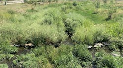
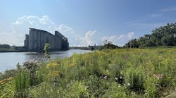
“Four slopes were stabilized in the floodway of Fee Fee Creek. In the creek, erosion control was used to create habitat for fish. The rock drop structures were used to allow water to step down in the creek, creating deeper pools for fish and fauna,” says Koscielski. “At the Missouri River bluff area, a northern-facing slope was retained. The terrain marks the bluffs of the Missouri River floodplain.” In another area, he says, “Four slopes were placed at the two-cell box culvert at Louiselle Creek. Two walls were on the upstream end and two slopes on the downstream end. The slopes transitioned from near vertical to 3:1 slopes.”
Gershenson knew that the City of Maryland Heights engineers, in conjunction with Koscielski, had called for using a “living wall” system to stabilize the slopes on the project areas. The Tensar Sierra Slope system provided a solution. The mechanically stabilized earth system consists of galvanized wire facing components connected to a high-strength Tensar uniaxial geogrid.
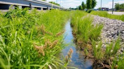
In March 2017, construction began on the greenway extension to provide continuous connection between the recreational complex and the park. One of the first challenges to be conquered was drainage on the slopes that were used to retain the Missouri River bluffs, where the walking trails would run.
“We had to get rid of a water seepage problem that was found because of the soil above the bedrock. We had to install a geosynthetic drain. There’s a poly pipe at the base and poly sheeting that runs all across the back. This provided a flow path for any water that should hit the drain mat. Once the water meets the geosynthetic drain, it drains to the bottom pipe and that draws it away,” explains Gershenson.
The drain was used in conjunction with interception ditches on the high side of the reinforced slope, adds Koscielski. The drain was placed under the trail as a redundancy to allow water to drain off the slope in wet spring conditions.
The 20-foot-wide slope with a 20-degree batter needed strong reinforcement. A cast-in-place concrete wall would not have worked, and the variety of curves and heights would make most other systems cost prohibitive. The Sierra Slope system, however, is made to be installed in such challenging grade separation projects as this one.
“The reinforcing grid runs horizontally back into the slope,” says Gershenson. “The height of the reinforced slope was over 30 feet tall, and the length of the geogrid is directly proportional to the height.”
City officials wanted the system to blend in with the environment with lots of green plants on the face of the wall. Because the slopes would be planted after stabilization, the landscape architect called for site soils to be blended and used when the 18-inch basket face system was installed and planted. Because the rough grading had to take place approximately six months before the Tensar Systems could be built, the contractor blended the soil materials and covered and stockpiled them for later use.
The McKelvey Woods trail project was finished in March 2018. On the southern and western exposures, sideoats grama and little bluestem were hydroseeded. Virginia wild rye and Pennsylvania sedge were hydroseeded on the north and eastern exposures, and Virginia creeper was also planted.