The case studies in this article focus on channel stabilization and erosion control along streambanks and other waterways. Channel stabilization and repair usually calls for the use of a channel lining. These safeguards fall into two major categories—soft and hard.
Soft armor, also referred to as flexible or green techniques, consist of grass or vegetation that is established with the help of erosion control blankets, turf reinforcement mats, or geogrids filled with soil. Grass channels that prevent erosion can be installed with little difficulty and are rather easy to maintain.
When the velocity of water flowing through a channel is greater than a vegetated lining can withstand on its own, however, hard armor such as riprap, concrete, or geosynthetic channel linings may be used. This hard armor, being inflexible and not allowing water to infiltrate, can also increase the velocity of flow.
Installing hard armor requires consideration of compaction, proper installation materials, and bedding. To prevent scour and undercutting, materials may be anchored down in a variety of ways.

Carthage Pike, IN
Many states have regulations regarding widening a stream channel, straightening a stream, dredging, building permanent structures like docks and boat loading ramps, altering any wetland, putting in utility crossings, or any type of streambank stabilization. Permits are required and it is recommended that an experienced professional designs the system.

Carthage Pike, IN
Basic Flow Calculations and Manning’s Equation
When engineers design for an open channel, ditch, or swale, they use basic flow computations, including Manning’s Equation. The problem is that Manning’s Equation assumes a constant uniform flow rate at a specified slope. There are many configurations that can alter this assumption. The downstream flow restrictions and how the channel bends will alter the constancy, along with any inconsistencies in the channel width or slope. Man-made structures in a river can alter the flow rate, such as culvert entrance and exit losses and headwaters at culverts or bridges. Basically, anything uneven or unexpected adds to the difficulty of using Manning’s Equation.
Therefore, except for educational purposes or developing a rough estimate, one of the environmental planning or engineering programs should be used instead. The US Army Corps of Engineers has developed several water surface profile programs that can handle variations in natural flow values (HEC-2 or HEC-RAS). Other agencies like the Natural Resources Conservation Service (NRCS) have programs used for basic flow computations.
Erosion Control and Channel Stabilization
There will always be limitations that will affect a design. Designers need to consider whether the streambanks are in a location where they can be easily maintained or inspected. Soft or flexible linings tend to need more maintenance and must be inspected more often to ensure they’re not damaged or overstressed. On the other hand, hard or more permanent channel linings can result in loss of habitat. In spite of the best-laid plans, hard armor can also be damaged due to settlement, scour, or undercutting.
The depth of a channel lining and providing the correct coverage will help prevent erosion and encourage good plant establishment. Channel bottom erosion can be the result of channel grade and liner not being appropriate for the amount of runoff. Although riprap seems fairly “bullet proof”, so to speak, a steep slope not accounted for correctly, or riprap too small for the job, can cause shift to occur, obstructing channels or even creating further damage.
Muddy River—Cooper Street Bridge
Moapa Valley in Nevada has a history of flooding and severe storms that date back as far as 1906, when the peak discharge was estimated at 8,800 cubic feet per second (cfs). Peak discharges over 8,000 cfs that regularly damaged rail road structures were not uncommon from 1906–1937. But 1938 brought the largest general flood recorded at that time for the Muddy River basin, with peak discharges as high as 15,000 cfs at Caliente.
Flooding continued over the years. The Clark County Regional Flood Control District and Clark County Public Works eventually designed a flood control plan, to be carried out in several phases. On the Muddy River at the Cooper Street Bridge, the project spanned more than 10 years.
Grant Tokumi, engineer and site designer with GC Wallace Inc. (GCW), a civil engineering firm in Las Vegas, NV, designed the Muddy River—Cooper Street Bridge rehabilitation project. “The widening of the Muddy River was more of a flood control measure to keep the storm flows contained within the channel,” he explains. “Historically, the adjacent properties and structures would persistently flood when the river swelled up during storm events. This project was the first phase of a much longer plan for river widening to mitigate the flooding along the Muddy River.”
Tokumi says the length of the project on the river spanned 4,600 feet, or just under a mile. The entire length was widened, ranging from 189 feet at the upstream end to 150 feet at the Cooper Street Bridge itself to 400 feet downstream.

Installing gabions near the Cooper Street bridge
In addition to the Muddy River being widened, plans were designed to replace the Cooper Street dipped roadway or low water crossing with an elevated bridge crossing.
Resident project representative Tony Williams, APWA, CPII, of Harris & Associates’ Las Vegas office simplified this part of the plan. “The Cooper Street Muddy River crossing was actually a low water crossing with the river going under the roadway through concrete box culverts during normal flow. During higher flows or following heavy rain, the flow was over the roadway. The existing river was very narrow and lined with heavy vegetation. The new bridge structure is approximately 20 feet above the new concrete channel invert.”
The Muddy River remained true to form and forced construction to temporarily shut down. In spite of the river being channeled into a 60-inch culvert, the construction site still flooded in September 2014.

The finished channel
Clark County was involved in providing erosion control at the bridge site and along the banks of the Muddy River.
“The rectangular concrete channel was constructed through the bridge section of the project, vertical concrete walls on concrete footings with concrete invert slabs between the walls,” says Williams. “The trapezoidal channel has sloped walls upstream and downstream of the rectangular channel.”
The concrete portions served to make the channel narrower in the vicinity of the bridge span, adds Tokumi. “The concrete also served as erosion control near the bridge.”
In addition to the concrete structures, gabions from Maccaferri were installed, along with riprap to stabilize the banks.
Carlos Andrade, Arizona and southern Nevada area manager for Maccaferri, explains how the different modules came together. “The project starts upstream with a trapezoidal gabion mattress channel 359 feet in length, to connect to the concrete channel that transitions from trapezoidal to rectangular, then crosses under the new bridge and transitions back to the trapezoidal shape, with a length of 1,484 feet. The concrete channel downstream connects to a trapezoidal gabion mattress channel that runs for 100 feet, then continues with riprap bank protection for about 1,130 feet on the east bank and about 2,050 feet on the west bank.”
The Maccaferri gabion mattresses were placed over a layer of Type II gravel. The gabions are PVC coated, and on this project they were connected with stainless steel Spenax rings to withstand the inimical soils of the area. A nonwoven geotextile (Maccaferri MacTex N47.1) was installed underneath the gabions and mattresses.
“About 6,900 cubic yards of Maccaferri 1.5-foot-thick gabion mattresses were used for the channel linings,” explains Andrade. “And about 1,300 cubic yards of 3-foot-tall gabions were used for the cutoff walls at the beginning and transition of the channel and toe of riprap bank protection.”

ShoreGuard installation
Finally, the plans included a curved two-span cast-in-place (CIP) post-tensional concrete box girder bridge to span over the Muddy River. A CIP bridge was constructed on temporary falsework using wood forms. The CIP bridge is constructed in stages, explains Eric Giles, structural engineer with GCW: “The soffit (bottom slab), girders or longitudinal walls spaced across the width of the bridge structure, and the top deck (driving surface of roadway) form boxes.
“Inside the walls of the bridge are galvanized metal ducts, which allow numerous post-tensioning cables to be added after the concrete has hardened. These cables are stretched much like a rubber band. When released, the cables put compressive stresses on the concrete to give it much added strength,” says Giles.
Santa Clara Valley—Page Ponds
Santa Clara County, CA, covers some 1,300 square miles, making it the largest of the nine Bay Area counties (population 1.8 million). Historically, communities in Santa Clara County relied on groundwater, beginning in the 1850s when some of the first wells were drilled.
In the 1920s, however, more water was pumped from the aquifers than nature could replace, and the groundwater levels dropped. The Santa Clara Valley Water District was formed in 1929 with objectives including groundwater management. Other functions of the district include protecting surface waters, increasing overall water supplies, and conserving, managing, and storing water for functional and beneficial purposes.

Santa Clara Valley, CA
Groundwater accounts for 50% of the water used today, with the remaining 50% coming from imported water. The Santa Clara Valley Water District has several groundwater recharge ponds. Overall, there are 100 or so percolation ponds totaling nearly 400 acres in the county. In addition to the 90 miles of creeks that feed the ponds, additional water is brought in from state and federal water projects. Of this water, 24% goes into the percolation ponds and to the water treatment plants. The ponds filter some 150 million gallons of water a day that then drains into the aquifers to later be mined by municipal systems or private wells.
Chad M. Grande, senior field operations administrator for the West Valley/Lower Peninsula watersheds of the Santa Clara Valley Water District, says the ponds began as a water distribution system for farmers to move water to their fields. What are now the Page Ponds came from the Page Farms, and so on.
“The groundwater recharge system in this area consists of three pond groups, which start with the desilting basin,” explains Grande. “The desilting basin contains a maze of sheet pile walls. The water is transferred through the canal from local or imported sources to the desilting basin, where the water slows and weaves through the maze of sheet piling. The desilting basin allows silt and turbidity to fall from the water before it proceeds to the groundwater recharge ponds. The process of cleaning the water before it arrives in the recharge ponds reduces the frequency of pond cleaning.”
He notes that the walls in the desilting basin were once made of redwood and needed replacing every seven to 10 years. “There were also erosion issues on access roads and the perimeter of some of the ponds, and sheet piles were used to make these repairs.”
The district had a previous working relationship with Crane Materials International (CMI) of Marietta, GA. Because the district knew it had a challenging situation, with the walls being in constant contact with the groundwater, it wanted to use something besides steel that would still have long-lasting durability. The three Page Ponds each had their own erosion challenges.
Mike Threde of CMI explains the assessments of the ponds. The maze-like configuration of the walls forces water to spend more time traveling around before it exits. “ShoreGuard SG-325 was used on the interior of the ponds as a baffle wall,” explains Threde. “This is a light sheet, but was an appropriate selection because a sediment wall that has equal amounts of water on both sides doesn’t really need a lot of strength.”
ShoreGuard SG-525 was used to control the erosion problem the district was having on the bank of the one pond. This was an area with no vehicular traffic on the top of the bank.
However, on one bank, the district has heavy maintenance vehicles driving near the edge at the top of the bank, so a heavier sheet piling was chosen. “The ShoreGuard SG-625 is a stronger sheet and is also anchored to the wall back with concrete anchors,” says Threde. “The concrete anchors are placed in the ground roughly 10 feet behind the wall. A tie-rod is then connected from the front face of the wall to the concrete anchor, thus securing the wall from deflecting forward during heavy loading.”
All of the ShoreGuard vinyl sheet piling is corrosion and UV resistant and impervious to marine worms. Each type is manufactured using more than 90% post-industrial recycled materials.
Installation presented a few challenges of its own because of the large number of boulders present in the area. In some places pre-trenching was required.
“Usually sheet piles are driven or vibrated into the soil,” says Grande. “The soil compaction in this area would not allow this method of installation due to the large cobbles. We assembled the sheet piles into panels, dug trenches, and lowered the panels into the trenches.”
In addition to the groundwater recharge ponds, Santa Clara Valley Water District also maintains an advanced recycled water purification center and a state-of-the-art water quality laboratory. It manages 10 dams and surface water reservoirs and three water treatment plants and more than 275 miles of streams. The district is also in charge of the county flood control program.
Carthage Pike, IN
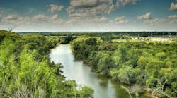
The Big Blue River watershed, part of the great Mississippi River watershed, drains approximately 54 square miles of Henry and Rush Counties, located in east-central Indiana. Rush County sits directly in the heart of the state’s transportation infrastructure. Located between Indianapolis; Cincinnati, OH; northern Kentucky; and Dayton, OH, the area moves freight via an ample highway system, railroad, and several ports, including the Port of Indiana.
Several years ago, Rush County and Indiana Department of Transportation (INDOT) realized erosion was occurring along the banks of the Big Blue River close to Carthage Pike roadway. The erosion was substantial enough that if nothing was done, it would eventually endanger the Pike.
“Carthage Pike sits atop of the bank of the Big Blue River,” says Neal Bennett, environmental scientist with Butler, Fairman and Seufert Inc. of Indianapolis. “There was severe erosion. It was definitely eroding under the guard rails. There was nothing holding them down. It would have begun undercutting the road if nothing was done.”
Andrea Langille, road project manager with Butler, Fairman and Seufert, explains the three phases of the Carthage Pike Roadway Improvement project. “The intent of the roadway project included some widening, roadway realignment both vertical and horizontal, and pavement reconstruction or rehabilitation as needed,” she notes.
The overall Carthage Pike Roadway Improvement project extended from the town of Carthage limits to SR140 and was split into three phases. The first two phases were construction projects in 2009 and 2011. Langille says that during the construction of phase two and the design process for phase three—which includes the area where the slope stabilization ended up being needed—failure of the existing bank of the Big Blue River was noted. The bank was in close proximity to Carthage Pike and was threatening the stability of the roadway. Phase three was designed to include the slope stabilization.
Engineers considered moving the road, but because of a nearby cemetery that would also have to be moved, that was not a practical alternative.
Utility lines overhead posed another slight challenge, says Bennett. There were height limitations on all shrubs, and no trees could be used. Instead, designers had to choose low-growing plants that would be grow in soil that was “highly erodible.”
“You couldn’t just throw in wetland plants,” he says. “This wasn’t wetland, even though it was right on the river. I studied a lot of soil taxonomy and we ended up using riparian and prairie grasses—because they root deeply—and a lot of low-growing shrubs.”
The engineers had also encountered a sediment island located in the Big Blue River near the Carthage Pike. Channels having supercritical flow are much more difficult to design for than low-velocity streams, and in this area there was little erosion control upstream of the project area. Sediment was being deposited in an area of the stream landward of where the river widened. Eventually water was being forced under and landward of the area and creating a small island.
“We had to slow the water velocity,” explains Bennett, “and try to get a uniform channel width through there. The idea was to move the thalweg away from the road without damaging the way the stream works.”
Site superintendent Gary Davis of Rieth-Riley Construction in Indianapolis took care of removing the 100- by 400-foot sediment island by using an excavator. “The sediment island was removed by tracking an excavator out on the island and working it toward the riverbank until we were able to throw the material onto the banks and push it away with a bulldozer,” he says.
The goal of this project was twofold: protect the Carthage Pike roadway infrastructure and alleviate erosion along the streambank of the Big Blue River in that area. Bennett recapped that the “main concept of the project is to recapture pre-erosion bank conditions.” This included a 2:1 slope or flatter and vegetated slopes.
Hard armor was installed in the form of 24-inch A-Jacks, manufactured by Contech Engineered Solutions. A-Jacks concrete armor units interlock to produce a pliable segment that resists water energy, allowing it to protect against scour and erosion.

A-Jacks above and below the water level provide scour protection.
“Basically we were creating a new toe-of-slope,” says Bennett.
To install the A-Jacks, an area 2 feet deep and 2 feet wide was excavated and a stone bedding liner put down. The lower 12 inches of the A-Jacks was buried below the water level for scour protection. Geotextile was then wrapped around the backside of the units, and backfill was placed behind them.
Another major hurdle for Davis was that the plans called for construction to be undertaken only during low flow periods. “It was a challenge to work in the river area, as we had rain quite frequently during this time of year and we had to pull the pumps every evening and remove them from the river area while no one was onsite,” he explains. “During some of the rain events we were not able to work and had to wait, sometimes for a few days, to be able to pump the water down to work again.”
In a few areas along the river, agricultural runoff had caused erosion channels to develop. The 2-foot-wide channels were 3–4 feet deep in some places.
“We designed subsurface scour protection for these channels,” says Bennett. “Six-foot-wide hard-armor strips were incorporated into the design for the agricultural runoff, installed below the soil to stop the runoff from eroding more.”
As it turned out, the agricultural land became the temporary access point rather than crews moving equipment and people over or through the river to be able to work. “The site was made accessible by building a temporary stone road back to the river,” says Davis. “After work was complete, the road had to be removed and topsoil put back in place for the farmer.”
Bennett acknowledges that the project posed some challenges. “Sometimes these make it prohibitive to even do in some cases. Where some agencies or companies would rather dump riprap down and be done with it, we didn’t want to do that. For one, it’s not good for the aquatic environment, and also it’s very temporary. In 10 or 15 years you’ll just have to add more riprap!”