The trouble with stormwater runoff is that it travels along the ground surface and over pavement, picking up sediment and other contaminants as it goes. A well-designed surface water runoff collection and drainage system will funnel runoff from relatively large areas into individual collection points such as inlets and drains that direct the concentrated flows into transit structures such as storm sewers or underground storage tanks.
Because surface water runoff contains suspended soil particles and other impurities, it often needs to be filtered before its eventual final discharge into a natural body of water. These filters are designed to capture, absorb, and otherwise remove the contaminants from the surface water to make it clean enough to meet permitted discharge water standards. Inlet protection devices are designed to perform this filtration. These can be temporary measures, such as those typically used on construction sites where the ground surface has been disturbed and bare soil susceptible to large amounts of erosion has been exposed. These temporary measures are put in place until the construction effort has been completed and then removed or left to biodegrade.
Post-construction conditions are less susceptible to erosion and sedimentation in the short term, but stormwater management must be designed to manage runoff effectively for the long term (as measured in decades). Post-construction measures can include more permanent structures such as detention basins with specially designed and constructed outflow and discharge structures. Permanent controls also include appropriate site elements such as final development grades that minimize runoff, the use of porous pavements to infiltrate runoff, bioswales to trap and infiltrate sediments and pollutants, and hydrodynamic separators that use induced cyclonic separation on incoming flows to remove contaminants.
In addition to suspended sediment, various types of pollutants (oil, grease, fuels, or other hydrocarbons) need to be removed prior to final discharge. Many of these pollutants and chemicals adhere to suspended soil particles and are removed with the sediment by filtration. To remove the rest, inserts containing absorbent media are needed to effectively capture them.
These specific traps and filters are only a small part of the overall erosion and sedimentation control plan for any site. Proper vegetative ground cover, carefully designed runoff flow patterns, diversion and storage structures, and emergency overflow devices that safely handle excessive flows from storms that are larger than the design storm are all required for a complete surface water runoff control plan. Furthermore, each type of site (park lands and greenspaces, campuses, commercial and business parks, residential housing developments, shopping centers and big box stores, etc.) will require different kinds of sedimentation and erosion controls.
Design and construction are not the end of it. Even the best designed and built erosion and sedimentation management system requires appropriate maintenance. The long-term clogging of filtration systems is an ever-present problem, which can be avoided by regular and frequent cleaning or replacement. Time and money will have to be budgeted for what is typically a manual operation. Monitoring of a system’s effectiveness will also have to be performed long after construction is completed. This can involve the use of continuous monitoring devices as well as regular sampling and testing of effluent.
Permitting, NPDES, and the SWPPP
What standards does a site’s erosion and sedimentation control system have to meet? What regulations govern their design, construction, and operation? Man-made discharges to natural bodies of water are governed by the requirements of the National Pollutant Discharge Elimination System (NPDES).
As with most environmental regulatory programs, the federal EPA establishes standards and requirements, and in most cases the state environmental agencies perform enforcement and can mandate standards that are stricter than those of the federal government. The NPDES program governs non-agricultural sources of concentrated (point-source) and nonpoint-source surface water discharge into US bodies of water. It requires those performing the discharge to utilize various control measures, structures, and technologies to intercept and remove sediment and other pollutants from reaching surface waters. These procedures and methods are described in more detail in the discharger’s NPDES permit. The responsible parties must obtain an NPDES stormwater permit prior to discharge. Under the permit, the discharger must utilize stormwater pollution prevention plans (SWPPPs) or permanent stormwater management programs that utilize best management practices (BMPs). These BMPs are typically defined in detail by state regulatory agencies and are used to effectively minimize or completely eliminate the discharge of pollutants to surface waters. NPDES permit regulations govern the following types of stormwater discharges:
- Operators of municipal separate storm sewer systems (MS4s) located in “urbanized areas” and dischargers to an MS4.
- Most industrial facilities that discharge to an MS4 or to waters of the US. However, industrial activity (except construction) may be designated as having a condition of “no exposure” if the industrial materials and operations are not exposed to stormwater, and therefore may not need to obtain stormwater permit coverage.
- Operators of construction activity that disturbs 1 or more acre of land, or current construction sites that are less than 1 acre if they are part of a larger planned development.
NPDES Phase I permits regulate stormwater discharges from medium and large MS4s, construction activities of 5 acres or larger (or less than 5 acres if part of a common development), and industrial activities. Phase I MS4 permits are issued as individual permits. Phase II permits cover the regulations to stormwater discharges from small MS4s and construction activities that disturb equal to or greater than 1 acre.
ACF Environmental’s Gratemaster
A SWPPP is prepared for a site prior to construction to show how that site will meet the requirements of the NPDES permit. A SWPPP includes narrative description and drawings or maps showing how the site owner is going to meet the permit requirements. The narrative describes the site before, during, and after construction. The portion of the narrative dealing with construction activities should describe the sequence of soil-disturbing activities, the areas where each activity occurs, and each area’s associated runoff characteristics (runoff curve number, size of each area in acres, the size of the watershed(s) associated with the site, location (northing, easting, and elevation) of each outfall with a description of the outfall’s structural type, and existing site conditions with regard to soil and surface water discharge.
The SWPPP should describe in detail the types of controls to be installed and constructed, both temporary controls during construction and permanent controls after construction. The description should include other controls such as a spill countermeasures plan, waste management and disposal, and dust control. Maintenance and inspection procedures need to be included, along with methods to manage any non-stormwater discharges.
Lastly, the SWPPP should include a map or set of drawings showing the location and extent of the site, any adjacent natural bodies of water, and where they are receiving the discharge. Further drawings should show drainage flows and watershed boundaries, slopes and flow gradients, undisturbed areas, limits (both horizontally and vertically) of soil disturbance, and locations and types of controls including areas of surface stabilization.
Design Methodologies: Runoff Estimates and Erosion Calculations
Surface water runoff occurs both during construction when there is a large proportion of bare ground and exposed earth, and post-construction when ground has been seeded or covered with buildings, pavements, landscaping, and other structures. Total surface water runoff volumes, peak surface water flows, and estimated quantities of soil erosion need to be calculated for both situations.
Many runoff estimates are derived from the mythology developed for “Technical Release 55—Urban Hydrology for Small Watersheds” published by the US Department of Agriculture’s Soil Conservation Service in June 1986. Using these methods, total runoff is determined as a percentage of total rainfall (measured in inches). A watershed’s total runoff is a function of both the “initial abstraction” (losses deducted from rainfall prior to runoff such as immediate absorption into underlying soils, measured in inches) and its potential maximum retention (losses deducted from rainfall after runoff begins, also inches).
This second factor is in turn derived from the watershed’s surface runoff curve number (CN), an empirical value that gives a relative runoff value range from 0 (which results in zero runoff) to 100 (which results in runoff equal to the amount of precipitation) for different types of surfaces. A curve number is tied to a particular hydrologic soil group (designated A, B, C, or D, ranging from soils with high infiltration rates to soils with low infiltration and high runoff), the types and extent of surface vegetation, types of planting methods and other physical surface treatments, and the extent of impermeable surfaces such as pavements and rooftops. Even in most urban environments, this last condition is secondary to vegetated soil surfaces, making up a minority of the overall surface area of the watershed. Often a watershed serviced by a particular collection point is made up of a patchwork of different ground surfaces, types of vegetation, etc. In these cases, total runoff is determined by the weighted averages of the runoff curve numbers of each of the watershed’s sub-areas.
The total runoff is the amount of overland flow during the duration of the rainfall event (typically rated as a 24-hour period). This is different from the peak flow that occurs along with the time of peak runoff and concentration of flows into collection structures or natural waterways. Peak flow is a function of the time it takes for flows to concentrate over the various flow segments associated with the watershed drainage patterns added in sequence. This includes sheet flows that occur over sloped areas before concentration, shallow concentrated surface flows, and open-channel flows in man-made ditches or natural streams. Times of concentration are typically a function of surface roughness, flow gradient, flow length, and flow velocity. With the total time of concentration calculated, the peak flow can be estimated using this value along with the total runoff quantity and runoff area. The resultant peak flow is used to design the inlets, drains, and other flow control structures receiving the peak runoff.
Potential erosion rates, and the amount of sediment carried by the surface water runoff, are estimated using the Revised Universal Soil Loss Equation (RUSLE). This estimates the potential long-term average annual soil loss in tons per acre per year. The factors used to determine the average annual soil loss include rainfall intensity determined by geographical location, soil erodibility derived from the soil’s textural class and percent organic content, slope length and steepness, crop/vegetation management practices such as tillage, and physical surface support methods.
Using these or similar methodologies, the design engineer can estimate with a high degree of accuracy both the peak flows from the site’s design storm and the amount of sediment that must be intercepted. These values in turn determine the size of the inlets or drains and the types of protection best suited for them.
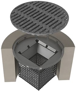
Combination inlet steel basket assembly
Temporary Erosion Control Measures
Doing nothing is often important when it comes to erosion control. That “nothing” means leaving wide areas of existing vegetation undisturbed. The resultant vegetative buffers are usually located around the perimeter of the construction
site. They are designed to remain undisturbed to protect existing natural features (trees, surface waters, etc.). Their natural characteristics are effective against erosion and the transport of sediment. Equipment movement and construction activities need to be kept clear of these areas in order to preserve them. These vegetative areas can be extended by the use of temporary seeding to stabilize the bare soil with vegetative growth.
Other installations around the perimeter of the job site might include silt fence or various types of berms such as fiber logs, compost-filled tubes, or manufactured wattles. Approximately 3 feet high, silt fence consists of panels of geotextiles affixed to wooden stakes. The fence is installed securely with the bottom edge of the geotextile trenched a few inches below ground surface. Located primarily down grade from the construction activities, silt fences are designed to intercept sediment being transported by surface water flows. Fiber logs (or wattles) can be similarly placed around the site perimeter in locations where silt fences are not feasible. Often made from straw, wood, or coconut fiber and geotextile fabric, they are placed directly on the ground surface to intercept sediment while allowing flow-through of water.
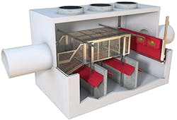
Nutrient Separating Baffle Box
Inorganic materials also make effective erosion controls. Rocks placed at a construction entrance can act as a rubble strip area to knock sediment off the tires and underbody of trucks entering and leaving the site; specially designed grates are also available for this purpose. Rock check dams are piles of rocks installed at regular intervals in the bottom of drainage swales. Acting as sediment traps, they need regular maintenance and cleaning out of accumulated sediment. Larger riprap can be used as armor against erosion caused by concentrated downslope flows and at the bottoms of channels against rapid downhill discharges.
Broad area erosion controls might include the placement of mulch over areas that have been seeded and are awaiting the establishment of complete vegetative cover. Consisting of wood fibers, compost, wood chips, straw, or hay, the layer of mulch reduces erosion by buffering the impact of from rainfall and runoff and provides protection and moisture for the establishment of vegetation. Hydraulic mulches or hydromulches are applied using hydroseeding equipment and are typically used in areas with steeper slopes or where equipment access would be difficult.
Circular frame catch basin
Included in the category of broad area controls are erosion control blankets and turf reinforcement mats. Made from jute, straw, wood, coir, or manmade fibers, they are woven into netting or matting that covers the entire ground surface, holding soil in place until vegetation is established. Blankets made from natural fibers decompose over time, while those made from high-density polyethylene (HDPE) fiber are designed as permanent soil and root anchors. They can also be installed along the bottom of drainage channels to prevent gulley formation.
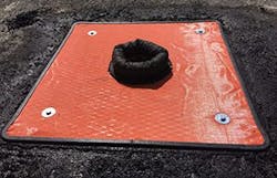
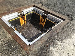
Lastly are those temporary measures associated with the protection of drainage inlets. As can be seen from the above descriptions of site erosion controls, inlet and drain protection is the last and most crucial defense against sedimentation. As such, it is the final block placed at the point of highest flow concentration. Though the inlets are permanent structures, they need to be protected from incoming sediment and contaminants until after the construction effort is completed and permanent erosion controls are established. These can include rock and compost bags or filter bags of various sizes and applications. The first are geotextile bags filled with rocks or compost that are placed in ditches or across the open mouths of the inlets and drains. The second are mesh bags, available in various configurations for different types of inlets, that act as sediment traps on their own. Installed in drains and across the openings of inlets, they serve to intercept and filter sediment-laden flows.
Permanent Sedimentation Control Structures
The primary (and simplest) permanent control structures consist of the final grading and earthwork onsite, including terracing, controlled runoff collection swales, flow discharge channels, and site regrading designed to minimize the effects of erosion on wide slope areas. Slopes can be stair-stepped to break up sheet flow and slow the velocity of concentrated flows.
More elaborate structures include concrete or brick retaining walls and gabion block walls. These are designed for slopes steeper than 2:1 to stabilize the slopes against mass movement, surcharge loads from additional soil placement of new structures, erosion, and sedimentation. These structures can be combined with vegetation to create tiered planters, vegetated crib walls, and planted gabions. Bare or planted, these features basically break up runoff and provide armor against its impact.
Soil surfaces can be permanently protected against erosion in a variety of ways. The simplest and most obvious way is the use of seed, mulch, and fertilizer to establish permanent ground cover. Other materials can also be used, such as cellular soil confinement grids and turf reinforcement matting.
Lastly, there is the use of permanent sedimentation and erosion control basins sized and designed to manage worst-case anticipated inflows from the engineer’s design storms and the transported sediment. These basins are typically designed to perform both flow detention to minimize peak discharge flows exiting the area, and to trap sediment to prevent it from escaping the site into nearby streams, rivers, lakes, and wetlands. In contrast to permanent detention basins, ponds that are solely for trapping sediment are referred to as sedimentation basins, and these are typically temporary basins serviced with appropriate control structures to manage inflows and outflows without scouring or causing additional erosion.
In order to effectively trap sediment, the surface area of the pond has to match with the peak inflow rate so that the pond can trap particles of a particular settling velocity. In addition, sediment ponds typically have to be elongated or equipped with baffles that direct the flows along circuitous routes within the pond to ensure that the sediment has time to fall out prior to discharge. Sediment basins by themselves are not 100% effective in removing sediment (effective in removing sediment only down to about the medium silt size) and so should be used in conjunction with other control structures. Furthermore, sedimentation ponds may require extensive surface areas to manage incoming flows and be of sufficient depth to allow for significant accumulation of sediment prior to needing a clean-out.
In keeping with the requirements of the NPDES, state, and local regulations, the installed erosion devices are typically inspected once every seven days and after significant rainfall events. These inspections need to be recorded and kept on file. Permanent control structures usually need to be inspected monthly for the first year of the post-closure care period, followed by monthly or quarterly inspections. Clean-out operations need to be performed as needed to ensure proper long-term function.
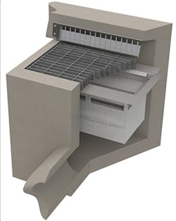
Gratemaster
Some Major Suppliers
ACF Environmental is a distributor of a variety of erosion and sedimentation control products, including inlet protection devices like the SiltSack, DirtBag, and GutterBuddy. The SiltSack is a temporary catch basin filter that prevents sediment, trash, and debris from entering a catch basin. It can be customized for both high flow and regular flow. The SiltSack can be manufactured with built-in curb deflectors and overflow holes. Though intended for temporary conditions, it can be emptied and reused for the life of the construction project. Made from recycled, synthetic fibers that filter out sediment and debris, GutterBuddy can be installed above ground and can be formed around or across the curb inlet. It is designed for curb inlets without grates to maintain critical water flow. The filtering action lets water freely flow through the fibrous material while stopping sediment and debris. Built-in overflows drain water more quickly during extreme events to prevent ponding.
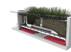
For post-construction stormwater control, ACF’s FocalPoint HPMBS is a scalable biofiltration system.
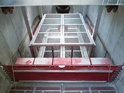
United Storm Water Inc. provides inspection, installation, and maintenance of its DrainPac catch basin and filtration system and Wing-Gate automatic retractable screens. DrainPacs are custom-designed and fabricated to meet specific requirements. Shapes and sizes include rectangular drop inlets, curb inlets, round inlets, sampling ports, drainage trenches, and ditch drains. Guillotine DrainPacs are designed with a metal mesh filtration panel that can slide out of the way to allow for easy cleaning. Weir DrainPacs contain a hinged filter mechanism, which allows easy opening and removal.
Hydra TMDL is a designer and manufacturer of automatic retractable screens for trapping debris before it enters curb inlets. Vertical “blades” keep solid material out of the storm drain inlet during dry conditions; the blades open automatically during flow conditions to allow water through; the opening is dependent on the amount of flow so that debris is still prevented from entering the inlet.
AbTech Industries produces catch basin inserts with Smart Sponge technology to absorb hydrocarbons, grease, and oil, and also to reduce bacteria levels. Smart Sponge fully encapsulates recovered oil, which prevents the absorbed oil from eventually leaching. Absorbed oils are transformed into stable solids for easy recycling. The Smart Sponge HM technology removes phosphorus and heavy metals.
Founded in 1997, Plastic Solutions Inc. provides structural plastic trash racks and debris cages for stormwater management at drain inlets.
Oldcastle Precast is a supplier of FloGard catch basin inserts and filters for locations subject to silt and debris as well as low-to-moderate levels of petroleum hydrocarbon (oils and grease). The inserts are available in sizes to fit most industry-standard drainage inlets, and are designed to capture sediment, debris, and trash as well as oils/grease from first-flush flows.
Suntree Technologies Inc. is a manufacturer of grates, catch basin baskets, skimmers, and baffle boxes. Suntree’s Nutrient Separating Baffle Box is a stormwater treatment system that utilizes a patented screening technology, enhanced three chamber separations, and inline installation. It captures sediment and suspends trash and debris in a dry state, which minimizes nutrient leaching, bacteria growth, and odors. Suntree’s NutriMax engineered wetland treatment system uses physical and biological processes to remove stormwater contaminants.
