Capping and closing a municipal solid waste (MSW) landfill can be a civil engineering challenge. The goal is to eliminate any need for further erosion control work on the site to ensure that the landfill keeps its structural integrity. True, landfill owners are required to adhere to EPA’s post-closure rules as defined by Subtitle D of the Resource Conservation and Recovery Act, which include maintenance of the leachate collection system, groundwater monitoring system, methane gas monitoring system—and, germane to erosion control activities, the final cover system. But having more structural work done after a landfill has been capped and closed can be costly and can damage the owner’s reputation.
This article includes an example of a project in which a landfill was capped to prevent outflow of leachate and sediment to groundwater sources. It also includes an example of a capacity improvement project, i.e., expansion of an existing landfill. Finally, it includes a section on designing and constructing the drainage system, which is a critical aspect of capped landfill design.
Protecting Groundwater in Florida
One of the biggest concerns with closing and capping landfills is keeping stormwater runoff from commingling with leachate within the landfill and contaminating nearby groundwater. In some cases, previously capped landfills need remediation to ensure that this problem does not continue to occur.
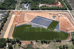
The 25-acre Saufley Field construction and demolition (C&D) landfill in Pensacola, FL, is one such case. The site was abandoned by its previous owner in 2008. Prior to the abandonment of the facility, the Florida Department of Environmental Protection (FDEP) documented numerous compliance issues since the site was permitted in 1990. The most severe noncompliance issues included operation of the facility at elevations approximately 40 feet higher than the permitted design height and the presence of hydrogen sulfide emissions. In fact, the air pollution associated with the operations of the facility became so extreme in 2007 that the Florida Department of Health issued a report declaring a public health warning with regard to elevated levels of hydrogen sulfide around the facility that were affecting the local community.
Additionally, the stormwater management design of the facility allowed both sediment and leachate to be released offsite, discharging into neighboring stormwater systems maintained and operated by Escambia County. Last but not least, groundwater contamination was recorded with elevated levels of aluminum, arsenic, and manganese, which also resulted in significant fines and violations.
FDEP and Escambia County leadership quickly realized that while this site remained open, it posed a threat to the environment and the health of the citizens surrounding the facility. The only answer to the problem was to close the facility, which in itself posed several significant challenges. Funds were not available to construct a closure, and the closure plan would involve significant site improvements to address the noncompliance issues. After evaluating other traditional soil cover systems in 2012, both FDEP and Escambia County selected the ClosureTurf system based on several criteria.
In addition to the Hydrofill, the Saufley Field landfill cap has
an impermeable, highly transmissive structured geomembrane and an engineered synthetic turf layer.
The system was determined to be the most economical approach to performing a closure. The “soiless” technology reduced the need for natural resources, i.e., soil for constructing the system. It would offer superior protection against erosion along slopes and in downchutes and perimeter conveyance channels. The system promised to reduce infiltration of stormwater into the waste, minimizing impacts to groundwater quality. The remediated site would also have enhanced emission control. And the system would reduce sediment loadings of stormwater runoff to the surrounding watershed.
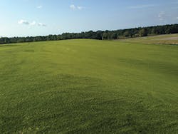
ClosureTurf is a patented three-component system consisting of Agru America Super Gripnet geomembrane, an engineered synthetic turf layer, and a specified infill, usually ASTM C-33 sand or Hydrobinder, a cementitiously bound infill for concentrated hydraulic flow areas. The impermeable, highly transmissive structured Super Gripnet geomembrane reportedly provides the highest interface friction values on the market. The engineered synthetic turf, consisting of UV-resistant, high-density polyethylene grass fibers, is designed to provide the natural look and feel of grass while protecting the geomembrane from extreme weather conditions and trafficking stresses over the long-term. The specified infill component is placed between the blades of the engineered synthetic turf and allows the system to sustain vehicle loading while also providing additional protection from weathering.
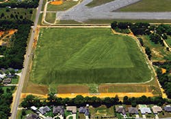
The 25-acre Saufley Field C&D landfill in was capped using a “soiless” system.
During construction, advantages included a reduced need for soil because the system uses a tufted geosynthetic erosion layer, i.e., engineered synthetic turf, and typically installs at least 40% faster than traditional vegetative cover systems. Over the long-term post-closure period and beyond, surface water rapidly drains off and is not restricted by the hydraulic conductivity of the cover drainage system, reducing cap infiltration and minimizing the impermeable layer hydraulic head and subsequent waste infiltration. The system is designed to be a virtually maintenance-free cover system, and its dust-inhibitive design eliminates the need for watering. Finally, the system is engineered with increased geotechnical factors of safety so it provides increased protection from sloughing and veneer failures.
The geosynthetic erosion layer concept used on the project yielded significant savings by eliminating the need for large amounts of soil that otherwise would be used to cover the geomembrane. The design also promises stability and resilience during severe weather events. The ClosureTurf maintained the landfill’s structural integrity during a historic flash flood event in April 2014. The system performed despite rainfall levels of 5.68 inches in a single hour and between 22 to 26 inches of rain over a 24-hour period. According to the National Oceanic and Atmospheric Administration (NOAA), it was the highest calendar day total dating to 1879. The NOAA HDSC Precipitation Frequency Map indicates that it was a 1-in-200-year to 1-in-500-year single hourly amount, and the 24-hour rainfall total was a 1-in-50- to 1-in-100-year event.
View of relatively clean stormwater runoff in a sediment pond at the Saufley Field landfill.
The system is also designed for functional longevity and significantly low long-term care costs. Most importantly, the system is expected to virtually eliminate any stormwater infiltration into the C&D landfill and resulting leachate outflows.
Supporting the Capacity Improvement Segment
A segment of the landfill construction market for which soil stability is critical is capacity improvement, or expansion. John Bolton, business director for Tensar Engineered Structures, says this segment is growing as landfill airspace is increasingly at a premium, which drives tipping fees higher. Permitting new cells can be challenging because protecting groundwater is so important and applicable regulations are very tight and well defined, he adds. This is why so many landfill owners seek to maximize the capacity of an existing landfill within its permitted footprint.
An additional factor driving expansion issues now, says Bolton, is the fact that some municipal landfills are taking coal ash, which is taking up more capacity. Ash used to be stored onsite at coal plants, but large energy producers that operate older coal-fired power plants are under new regulations to dispose of that byproduct in a different way to protect groundwater. “They’re having to find new ways to dispose of their coal ash, and landfill disposal is one alternative,” says Bolton. “It’s a new waste stream that did not traditionally go into landfills; their capacity is being taken up by new waste that didn’t exist for landfills before.”
Tensar developed its ADD3 Capacity Improvement Systems to provide lateral and vertical stabilization to perimeter structures of landfills that increase their capacity. “The overall objective of the stabilization of any cell is to protect the lining system,” says Bolton. “We design these structures with geosynthetic materials—primarily geogrids—and the system is designed to support the landfill cell so that the integrity of the liner is not compromised.”
The ADD3 system consists of four components, explains Bolton. The first is the conceptual scoping out of the project. Tensar evaluates several aspects of the project, such as property lines, cell dimensions, and topography. The second component is the design. Tensar looks at factors such as the loading conditions, the height of the landfill, and the strength of the subsurface strata beneath the landfill to develop design that meets the given design criteria.
The third part is the materials that go into the structure: primary HDPE geogrid, erosion control products, and welded wire forms or concrete block at the face of the mechanically stabilized earth (MSE) structure. These structures reconfigure the outboard slopes of perimeter berms to maximize the inboard airspace of the landfill cells. The fourth component is onsite assistance that Tensar provides the contractor during construction. Tensar representatives attend preconstruction meetings and make site visits to ensure that contractors install the ADD3 structures as efficiently as possible and to clarify any issues relating to the site plan.
Bolton reports that, as capacity improvement becomes more common, many landfill owners are open to the concept but need help from a third party to design an expanded structure that maintains structural integrity. “Landfill owners attempt to maximize what they get out of each cell and to go steeper or near-vertical with perimeter structures,” he notes. “Key drivers include the challenge of permitting a new cell, coupled with the difficulty of maximizing the airspace out of a given permitted landfill footprint. In places where you see the end coming soon for the cell and tipping fees are higher, you’re going to think of new ways to get more out of what you have.”
Pennsylvania Landfill Expanded Ahead of Schedule
An ADD3 system MSE berm was used to increase the capacity of Cumberland County, PA’s MSW landfill back in 2008. Plans to expand the landfill were submitted by the owner-operator, Interstate Waste Services, in August 2005 and by the Pennsylvania Department of Environmental Protection in December 2007. Hershey, PA-based environmental and geotechnical engineers ARM Group Inc., with assistance from Tensar International, developed the project design, as well as all permit and construction documents.
The design included a vertical expansion area over an existing landfill area and a lateral expansion area. ARM Group designed an MSE berm to optimize the volume and permitted the rechanneling of two streams to make the project feasible. The engineer had previously specified an MSE berm for a Chester County (PA) landfill expansion in 2004–2005.
The project was submitted for bid in January 2008 and awarded to Pavex Inc. of Camp Hill, PA. Pavex provided all earthwork services within the berm footprint. Elverson, PA-based Pickering Valley Landscape Inc. was subcontracted to install the Tensar products. The project was the second MSE berm installation for Miguel Servin, a project foreman for Pickering Valley who had also worked on the Chester County facility. Servin and a crew of nine built two MSE berms on the Cumberland County site, steepening the existing slopes with welded wire forms, reinforcing them with Tensar geogrids, and topping them with erosion control mats from North American Green, a sister company to Tensar.
The crew installed nearly 46,500 square yards of Tensar uniaxial (UX) geogrid and 21,800 square yards of Tensar biaxial (BX) geogrid in the process of constructing the berms over three months. One berm measured 1,100 feet long and had a maximum height of 58 feet, and the other measured 305 feet long and peaked at 19.5 feet tall.
“The project went great,” says Robbie Sochovka, Interstate Waste Services’ capital projects manager. “The technology demonstrates how we can help save valuable airspace. We’re very pleased with the product and engineering design.” Sochovka projects an additional 20 years of service for the landfill. The Tensar MSE berm was a first for Les Stotler, Pavex’s project superintendent and 30-year veteran of the site development industry. “The walls are beautiful,” he says. “And they were completed ahead of construction schedule.”
Designing for Release of Water
When it comes to protecting the structural integrity of landfills, it’s important to approach the tremendous power of water flow with a jujitsu-like mentality: leverage the momentum of the “attacker” to advantage rather than try to resist the momentum. Steven Mayes, P.E., senior technical manager for North America at GSE Environmental, notes how critical it is to provide a release mechanism for runoff seepage water through a capped landfill. Not doing so may result in soil sloughing—saturated soil loses its cohesion and falls down slopes in large sheets. Landfill sloughing has two causes: sediment buildup in swales, which timely maintenance prevents; and underdesigned landfill cap drainage system capacity.
Regarding the latter, Mayes refers to a New Jersey landfill that underwent significant sloughing due to clogged geocomposite material that prevented the inflow of runoff and seepage water into a perforated drainage pipe at the bottom of the slope. The landfill was referenced in a Geosynthetic Institute (GSI) report by Bob and George Koerner titled “On the Need for Water Release from Drainage Composites at the Toe of Slope.” In this case, the clogged geocomposite material caused increased pore pressure and, ultimately, caused the soil to begin sliding down the slope, notes Mayes.
“For everything associated with a landfill, the cap is the most visible to the public, and the public generally doesn’t want a landfill in its backyard,” says Mayes. “So if you think about the most scrutinized part of your design, that very well could be it.”
While the geocomposite material on the New Jersey landfill was indeed clogged, the bigger contributing factor was the manner in which the geocomposite drainage layer was terminated at the perforated drainage pipe. For terminating the geocomposite drainage layer, Mayes points out the importance of rapid and free water release from the geocomposite drainage layer into the drainage collection system such that buildup of hydrostatic pressure within the geocomposite drainage layer and the buildup of pore pressures within the cover soil are avoided.
Due to the underdesign of the landfill cap drainage layer capacity, water saturated the soil, causing increased pore pressures up to some undetermined elevation of the landfill slope. The resulting sloughing eventually caused large cracks in the soil, consequently causing a snowball effect by letting in even more runoff water and eventually leading to a veneer stability failure of the landfill cap.
Unit Gradient Method
In Mayes’ professional opinion, landfill capping drainage system design should be based on the Unit Gradient Method, a calculator for which can be found here. The most common design methodology, it assumes that cover soil is saturated, so the maximum flow velocity equals the permeability of the cover soil. “The Unit Gradient Method is the most straightforward, in my opinion,” he says. “You’re using the worst-case design scenario and designing around that; not all engineers take that approach, though.”
Another method, Hydrologic Evaluation of Landfill Performance, is not appropriate for landfill capping drainage design, according to GSE Environmental, because it uses the daily average rainfall in the water balance calculation, which does not simulate the worst-case condition.
The Unit Gradient Method gives engineers a great deal of latitude to design for site-specific water infiltration rates with reduction factors and safety factors.
Reduction factors include, but are not limited to:
- Lh: Drainage pipe spacing or length of slope measured horizontally—the spacing between lateral pipes in swales
- kveg: Permeability of the vegetative supporting soil, as measured by Length/Time; typically 1.05 or 1.1
- i: Hydraulic gradient—i = sin (ß), where ß is the slope, typically 3:1 (gradient = 32%)
Safety factors include, but are not limited to:
- FSd: Overall factor of safety for drainage 2.0–10.0, typically 2.0
- RFin: Intrusion Reduction Factor—adjusts for effects on infiltration rate due to variables such as the choice of geocomposite material; range = 1.0–1.2; engineers might opt for a slightly higher value to allow for short-term impacts on the infiltration rate under a 100-hour transmissivity test
- RFcr: Creep Reduction Factor
- RFcc: Chemical Clogging Reduction Factor, 1.0–1.2
GSI has a standard guide, GC-8 (Geocomposite 8), “Determination of the Allowable Flow Rate of a Drainage Geocomposite,” for which reduction factors to include based on the anticipated flow rate. According to Mayes, these factors can address uncertainty that may exist in translating the 100-hour transmissivity laboratory test results to field performance. Sometimes, though, engineers don’t use the Unit Gradient Method—or, if they do, they do not utilize appropriate reduction factors, says Mayes. He adds that this may have been the case on the New Jersey landfill.
Selecting Geocomposite Material
Mayes says that, in addition to the reduction and safety factors cited above, it’s important for engineers to take into consideration loads on the soil when selecting geocomposite material. For example, the load on soil above geocomposite material should not exceed the geocomposite material’s compressive strength. For instance, if the compressive strength of a geocomposite is 10,000 pounds per square foot, add in a minimum FSd of 2.0 and the load should not exceed 5,000 psf.
“Generally, when you’re trying to decide what type of geocomposite to specify, you have two considerations initially,” he says. “You’re always looking at its flow capacity, but you’re also considering the structural design of the geonet material itself because it has to accommodate any structural loading, and that’s not something all design engineers consider.” Besides structural loading, Mayes says that engineers may need to account for live loading from construction equipment such as bulldozers.


