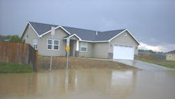
The Pacific Northwest recognized early on the negative effects of urbanization on receiving waters and has been a leader in the stormwater management field for decades. Initially driven by concerns about the impacts of urban runoff on threatened and endangered species in the Puget Sound area, this was later reinforced by the National Pollutant Discharge Elimination System (NPDES) permitting program.
Infiltration Design
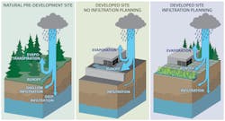
Over the last decade, MS4 Permits have started requiring the use of infiltration BMPs to mitigate the hydrologic and water quality impacts of development. From a surface water perspective, infiltrated runoff does not cause stream erosion, has no pollutant loading, and helps recharge groundwater.
Estimating Infiltration Rates
The starting point for designing an infiltration BMP is determining the infiltration rate your BMP is expected to have. Allowable methods have changed over the years, with some agencies requiring in-situ infiltration testing for all infiltration BMPs, and some allowing “grain size methods” to estimate rates in certain cases.
However, grain size methods for screening purposes should be avoided unless the soils meet all criteria for application of the equation being used. Reliance on grain size method results can backfire, which is why in-situ infiltration testing must be done to support the design process, with knowledgeable analysis of testing results.
The number of infiltration tests should scale with the size, complexity, and soil heterogeneity of the project site. Thoughtful testing and analysis methods can also indicate if groundwater was mounding during the test, and whether a formal mounding analysis is needed.
Once correction (safety) factors are applied, there are generally two ways an infiltration rate is used to help model and design infiltration BMPs: assume the infiltration rate is constant during BMP filling and emptying; or assume the infiltration rate varies (typically linearly) with water depth (pressure head) above the infiltration surface.
Knowing how the infiltration BMP will be sized is important when analyzing test data because the resulting constant infiltration rate will not necessarily be the same value as the variable rate.
Plan to Manage Plugging
Infiltration BMPs are susceptible to the same plugging by sediments and biofouling that stormwater filters are. Stormwater filters plug up; and infiltrating into soil is much like infiltrating into a filter. Therefore, pre-treatment to remove sediment is necessary to prolong the life of infiltration BMPs.
Plugging of the infiltration surface is the main reason that safety factors are used when sizing infiltration BMPs. Stormwater manuals often prescribe safety factors, but the safety factor really should scale based on the soil being infiltrated into.
For instance, when infiltrating slowly into a fine soil with a permeability not much higher than stormwater sediment, reducing the measured rate by a factor of 2-4 is acceptable. But, when infiltrating into coarser soil with a permeability much greater than stormwater sediment, a larger safety factor is warranted (some jurisdictions do set a maximum design infiltration rate). The level of treatment for sediment removal prior to infiltration should affect the safety factor, too.
Check and Address Groundwater Mounding
Infiltrating runoff sometimes causes groundwater mounding. As mounding increases, it can reduce the infiltration rate, cause seepage problems, and raise regulatory compliance concerns. Monitor groundwater during infiltration testing to see if it rises in response to the test. If so, the data can be used to help calibrate a mounding model.
In cases where mounding is an issue, a formal analysis and modeling (such as USGS’s MODFLOW) of the receptor soil/aquifer combination, as well as a fine-tuning of infiltration BMP flowrates and spacing can further avoid mounding problems.
Deep Infiltration
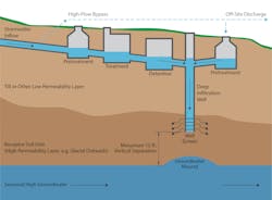
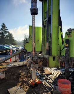
The use of deep infiltration to meet Low Impact Development and flow control requirements on projects has been increasing, particularly where surface soils have low permeability but overlie an unsaturated, higher-permeability soil. It’s sometimes feasible to bore through the surface soil and install an infiltration well in a more permeable receptor soil. Stormwater runoff is then routed into the well and infiltrated into the receptor soil.
The concept of deep infiltration is straightforward, but a system that reliably functions for decades requires some careful thought.
Although preferred methods vary, for deep infiltration testing and analysis in general accordance with Borehole Injection Testing and the Well Permeameter Method (USBR Test Method 7300-89) is recommended. After analysis of test data, the well permeameter equation can be used to estimate infiltration flow rates for other well diameters and screen lengths.
To prevent plugging, it’s critical to keep sediment out of deep infiltration wells. However, normally some runoff is allowed to bypass treatment BMPs during large storms. Directing untreated flow into infiltration wells will reduce their service life.
Another consideration is whether advance BMPs can be a source of initial sediment loading. For instance: Is that drain rock really clean? Should I specify on-site washing of drain rock? Will my bioretention mix initially leach sediment? Should I flush the system before connecting to infiltration BMPs?
Deep infiltration wells should be designed to:
- Include treatment to remove sediment for all flows to the well,
- Control the rate of flow into the well to the design rate,
- Reserve head to allow water levels to rise to counteract plugging,
- Prevent baseflows from entering infiltration wells, and
- Ensure the system drains down in a reasonable time.
Protect Your Infiltration BMP
Here are some other issues to be concerned about when constructing infiltration BMPs:
- Prevent compaction of the infiltration soil
- Protect the system from construction runoff
- Remove construction sediment from the upstream drainage system
- Specify and verify that the proper geotextiles are being used
Using the ‘Infiltration Cookbook’
Consistently achieving successful stormwater infiltration requires clear and comprehensive guidance for planning through construction. As part of the team preparing an updated LID Manual for the Port of Seattle’s Seattle-Tacoma International Airport (STIA), Aspect Consulting developed Standard Operating Procedures (SOPs) for shallow and deep infiltration systems.
The SOPs provide consolidated guidance for planning, testing, analysis, design, and construction of infiltration facilities.
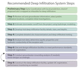
For example, the recommended SOP steps for deep infiltration are shown in the flowchart. SW
John Knutson is a principal engineer with Aspect Consulting. He has 29 years of experience leading stormwater, flood management, and habitat restoration projects for clients throughout the Pacific Northwest. He can be contacted at [email protected].
Published in Stormwater magazine, February 2022.
